ER5000 —
86
Installation Variations
Setpoint Wiring Variations
Analog Setpoint Source — Active PC or PLC D/A Card
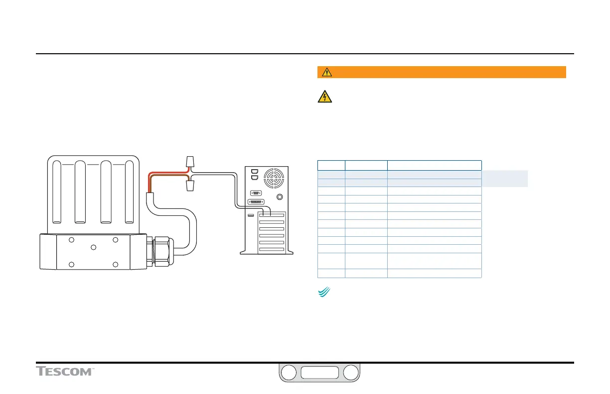
Figure 25 shows correct wiring to provide an analog setpoint from
a PC or PLC D/A card. In this conguration, the power is supplied
by the active D/A card.
RED
BROWN
PC
+ OUTPUT
-
OUTPUT
Figure 25: Active PC or PLC D/A Card Analog Setpoint
WARNING
The controller must be disconnected from the power supply before
any additional wiring or change to jumper configuration is
performed. Do not reconnect the power supply until all additional
wiring connections have been made and are properly installed.
Refer to Table 8 to verify correct wiring.
Table 8: Wiring for Active PC or PLC D/A Card Analog Setpoint
J3 Pins Wire Color Function
1 brown +setpoint input
2 red -setpoint input
3 orange +feedback input
4 yellow -feedback input
5 green -RS485 network connection
6 blue +RS485 network connection
7 violet +24V DC power
8 gray 24V return (power ground)
9 white +5V output (5 mA max.)
10 black analog signal/board ground
*11 *pink analog signal output
(active in Enhanced “F” models ONLY)
12 tan analog signal/board ground
NOTENOTE
CAUTIONCAUTION
WARNINGWARNING
Check that Jumper J6 (refer to Figure 19) is installed for
4–20 mA operation and removed for 1–5V operation. There is no jumper
on the 0–10 Volt ER5000 models.

 Loading...

