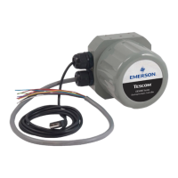
ER5000 —
82
Installation Variations
Power Supply Wiring — All Applications
All ER5000s, regardless of conguration or application, must rst
be wired to a 24V DC power supply, as shown in Figure 21.
POWER
SUPPLY
+24V DC
VIOLET
GROUND
GRAY
Figure 21: Wiring to 24V DC Power Supply
Refer to Table 4 to verify correct wiring.
Table 4: Wiring to 24V DC Power Supply
J3 Pins Wire Color Function
1 brown +setpoint input
2 red -setpoint input
3 orange +feedback input
4 yellow -feedback input
5 green -RS485 network connection
6 blue +RS485 network connection
7 violet +24V DC power
8 gray 24V return (power ground)
9 white +5V output (5 mA max.)
10 black analog signal/board ground
*11 *pink analog signal output
(active in Enhanced “F” models ONLY)
12 tan analog signal/board ground
WARNING
• Select wiring and/or cable glands that are rated for the environment
of use. Failure to use properly rated wiring and/or cable glands can
result in personal injury or property damage.
• Wiring connections must be in accordance with local, regional
and national codes for any given area. Failure to follow the local,
regional and national codes could result in personal injury or
property damage.
• To avoid personal injury resulting from electrical shock, never
connect the controller or associated equipment to a supply
source having a voltage greater than the maximum rated
voltage of this controller or the associated equipment. Make
sure that the components used in the electronic system are
compatible with and have the proper voltage rating.

 Loading...


