ER5000 —
109
Installation Variations
Wiring Variations for Additional Functions
Suspend Mode
NOTENOTE
CAUTIONCAUTION
WARNINGWARNING
This feature is only available on “F” models of the ER5000.
Suspend Mode is a new feature for “F” model ER5000s. When
Suspend Mode is activated, the Inlet and Exhaust valves remain
fully closed and the PID algorithm is suspended. This ensures a
completely stable state, with no unwanted response to system
noise, until Suspend Mode is deactivated. This feature is useful
for applications, such as calibrating a sensor or detecting a leak,
where total stability is required.
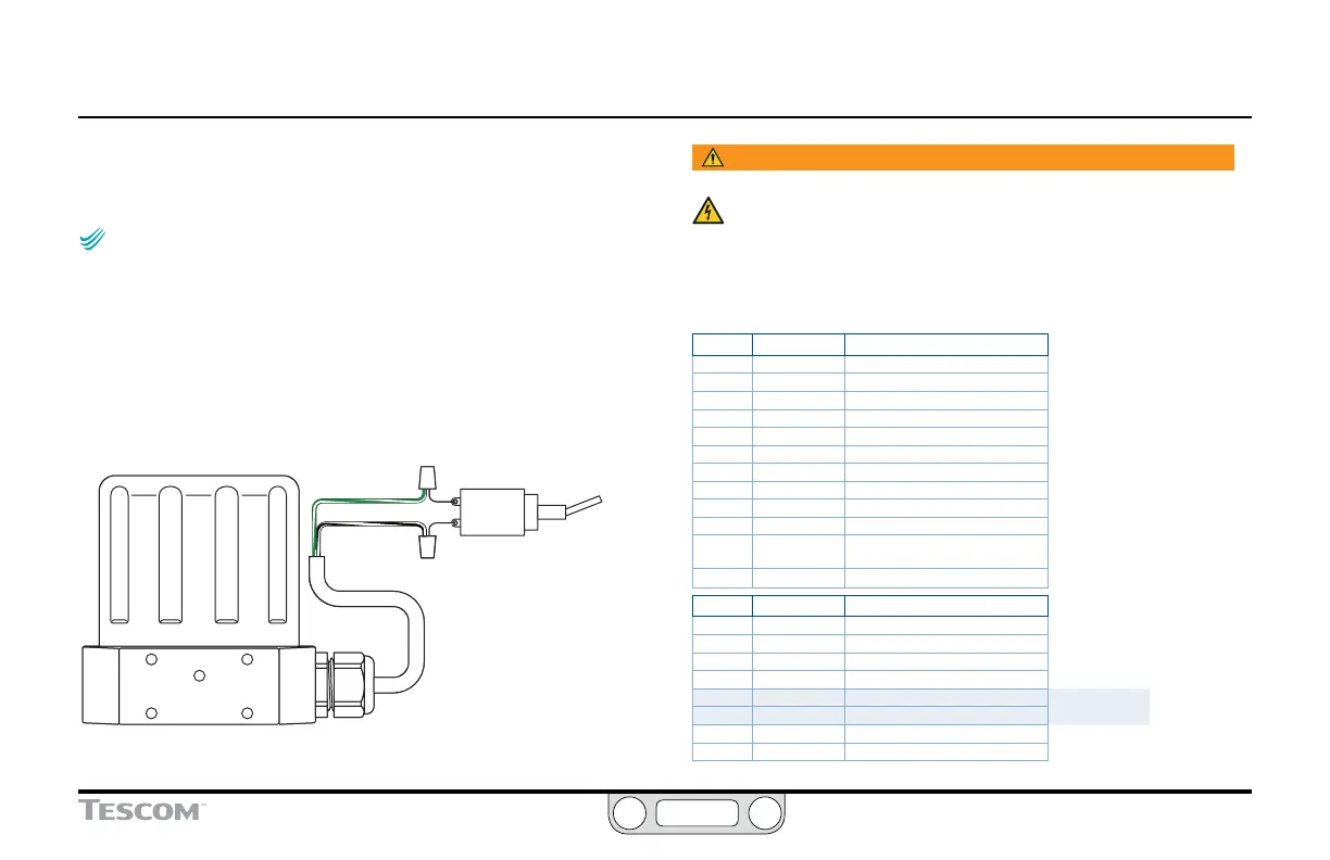
GREEN/WHITE
BLACK/WHITE
START/STOP
SWITCH
Figure 43: Suspend Mode
WARNING
The controller must be disconnected from the power supply before
any additional wiring or change to jumper configuration is
performed. Do not reconnect the power supply until all additional
wiring connections have been made and are properly installed.
Refer to Table 26 for correct wiring.
Table 26: Wiring for Suspend Mode
J3 Pins Wire Color Function
1 brown +setpoint input
2 red -setpoint input
3 orange +feedback input
4 yellow -feedback input
5 green -RS485 network connection
6 blue +RS485 network connection
7 violet +24V DC power
8 gray 24V return (power ground)
9 white +5V output (5 mA max.)
10 black analog signal/board ground
*11 *pink analog signal output
(active in Enhanced “F” models ONLY)
12 tan analog signal/board ground
J4 Pins Wire Color Function
1 brown/white +aux input #1
2 red/black -aux input #1
3 orange/black +aux input #2
4 yellow/black -aux input #2
5 green/white suspend control
6 black/white digital output/board ground
7 blue/white digital output #1
8 gray/black digital output #2

 Loading...

