ER5000 —
84
Installation Variations
Setpoint Wiring Variations
Analog Setpoint Source — Current/Voltage
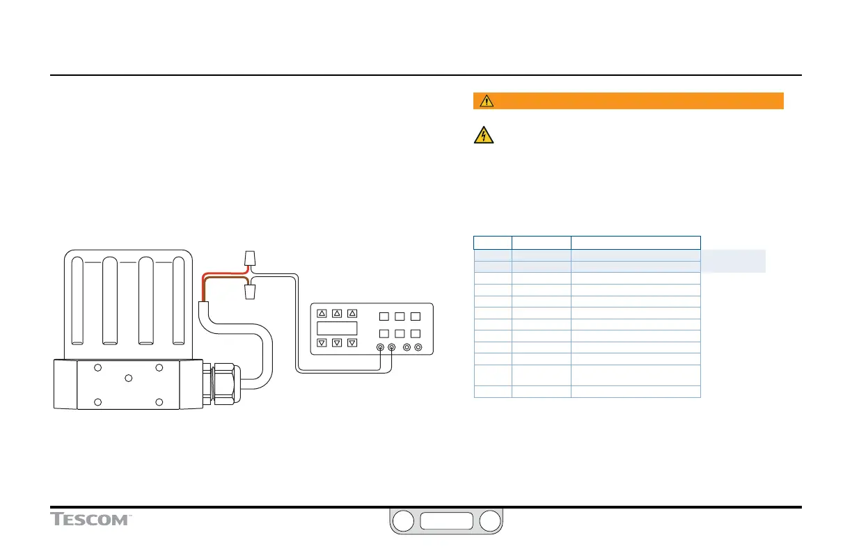
Figure 23 shows how to provide the analog setpoint from an
active variable current or voltage supply.
The negative (-) lead of your source connects to the red wire and
the positive (+) lead connects to the brown wire.
RED
SIGNAL SOURCE
4–20mA or 1–5V or 0–10V
BROWN
- OUTPUT
+ OUTPUT
Figure 23: Current/Voltage Analog Setpoint
WARNING
The controller must be disconnected from the power
supply before any additional wiring or change to jumper
configuration is performed. Do not reconnect the power
supply until all additional wiring connections have been made
and are properly installed.
Refer to Table 6 to verify correct wiring.
Table 6: Wiring for Current/Voltage Analog Setpoint
J3 Pins Wire Color Function
1 brown +setpoint input
2 red -setpoint input
3 orange +feedback input
4 yellow -feedback input
5 green -RS485 network connection
6 blue +RS485 network connection
7 violet +24V DC power
8 gray 24V return (power ground)
9 white +5V output (5 mA max.)
10 black analog signal/board ground
*11 *pink analog signal output
(active in Enhanced “F” models ONLY)
12 tan analog signal/board ground

 Loading...

