5 – 26
Section 5 • Maintenance/Service
VSS/VSM/VSH/VSSH • Installation, Operation and Maintenance Manual • Emerson • 35391SD
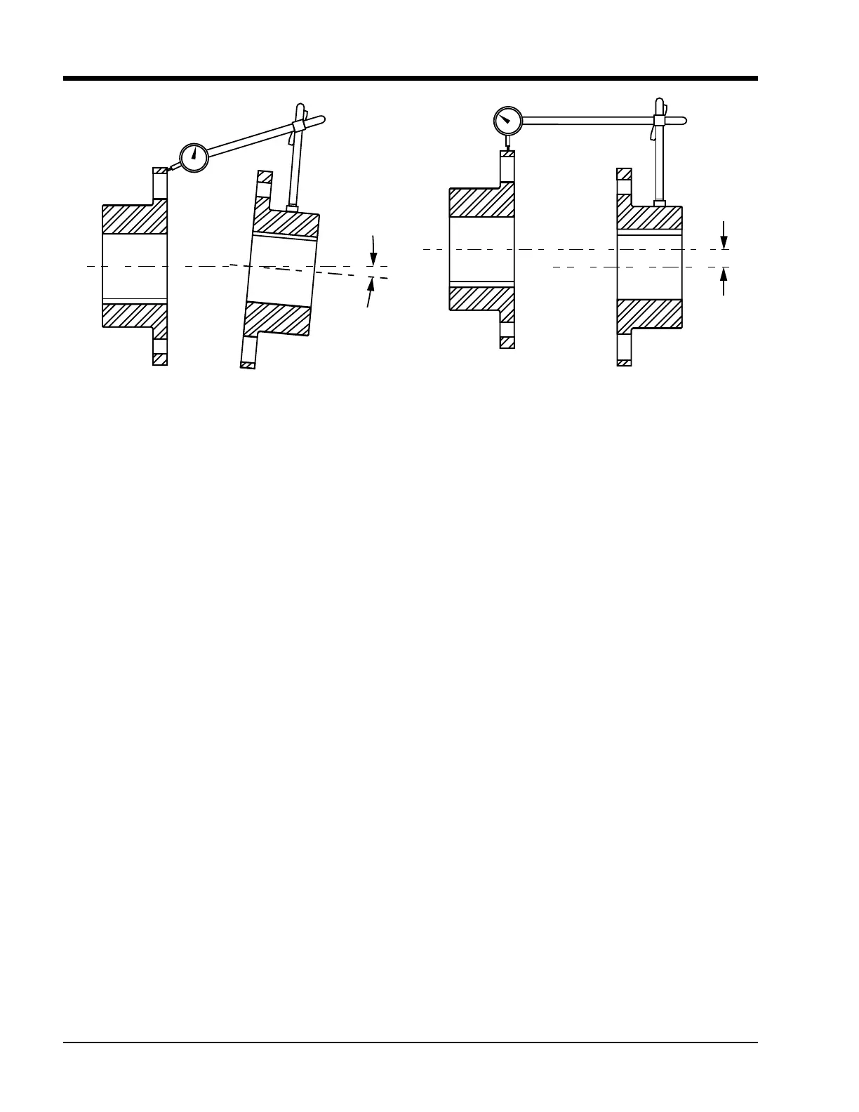
22. Angular Alignment. Rigidly mount a dial indicator on
one hub or shaft, reading the face of the other hub
ange. Rotate both shafts together, making sure
the shaft axial spacing remains constant. Adjust the
motor by shimming and/or moving so that the indi-
cator reading is within 0.002” per inch of coupling
ange, see Figure 5-18.
23. Parallel Offset. Rigidly mount a dial indicator on one
hub or shaft, reading the other hub ange outside
diameter. Indicator set-up sag must be compen-
sated for. Rotate both shafts together. Adjust the
equipment by shimming and/or moving so that the
indicator reading is within 0.002” per inch of the ax-
ial length between ex disc packs, see Figure 5-18.
With the coupling in good alignment the bolts will t
through the holes in the anges and the disc packs more
easily.
NOTE
All bolt threads should be lubricated. A clean motor
oil is recommended. On size 226 and larger, a link
must be put on bolt rst. Remove the disc pack
alignment bolt. Proceed to mount the second disc
pack to the other hub in the same way. Ensure that
the beveled part of the washer is against the disc
pack.
24. Install bolts and locking nuts to secure both disc
packs to center member.
25. Tighten locking nuts.
26. If room is required to install center member, adjust
hub position accordingly. If both the motor and
compressor hubs are straight bores, adjust either
hubs. If one hub is tapered and the other a straight,
adjust the straight bore hub.
27. Using additional supports supporting center mem-
ber. Install bolts and locking nuts to secure center
member to compressor hub.
28. Tighten locking nuts.
29. Position hubs, ensure distance between face of
both hubs is 5”.
NOTE
If there is waviness with the disc pack installed, adjust
distance accordingly until disc pack is straight.
30. Install bolts and locking nuts to secure disc pack to
motor hub.
31. Tighten locking nuts, see Table 5-5.
32. Perform hot alignment. Run compressor unit and
allow to warm up completely.
33. Power down compressor unit and re-check align-
ments. Loosen motor mounting nuts to add shims
or to adjust alignments as required.
34. Install coupling guard.
Figure 5-18. Angular Alignment and Parallel Offset
Angular Alignment Parallel Offset

 Loading...


