5 – 39
Section 5 • Maintenance/Service
VSS/VSM/VSH/VSSH • Installation, Operation and Maintenance Manual • Emerson • 35391SD
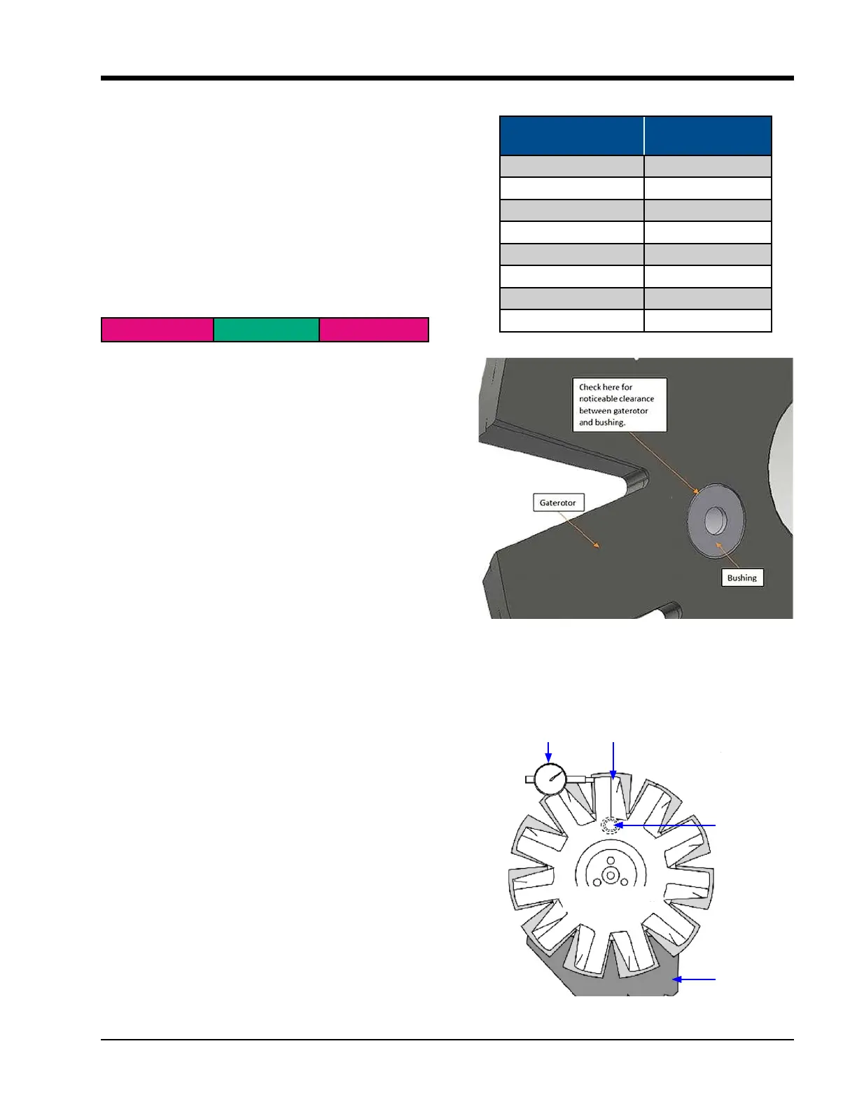
Table 5-12. Gaterotor Float
Model
Float
in. (mm)
VSM-97 - VSM127 0.045 (1.143)
VSM 71 - VSM 401 0.045 (1.143)
VSM 501 - 701 0.045 (1.143)
VSS/VSSH 291 - 601 0.045 (1.143)
VSS 751 - 901 0.055 (1.397)
VSS/VSH 791 - 1301 0.060 (1.524)
VSS 1501 - 2101 0.060 (1.524)
VSS 2401-3001 0.060 (1.524)
4. If it is easy to pull out the feeler gauge, then increase
the feeler gauge thickness by 0.001” and repeat
above steps 1-3. If it is slightly tight to pull it out,
then the clearance corresponds to the feeler gauge
thickness.
NOTE
Replacement gaterotors are the same dimensionally as
the gaterotors installed at the factory. Therefore, the
same shims can be reused when replacement is needed
to preserve the 0.003” – 0.004” clearance.
B) Gaterotor Float Measurement
1. Before doing any measurements, rst conduct a vi-
sual check to see if there is any noticeable clearance
between the gaterotor and its bushing, see Figure
5-32. If there is noticeable clearance, please contact
Vilter Service Department.
NOTE
The number of bushings on a gaterotor can be anywhere
from one to three.
2. To measure the oat between the gaterotor bush-
ing and the support damper pin (see Figure 5-34),
position a dial indicator at the tip of the support as
shown in Figure 5-33. Hold the gaterotor in place,
then gently move the support teeth back and forth
with two ngers (and record measurement). Refer to
Table 5-12 to nd the maximum oat value.
NOTICE
If clearance measurements are out of tolerance,
contact Vilter Service Department for further
assistance.
Figure 5-32. Visual Inspection Between
Gaterotor and Bushing
Figure 5-33. Gaterotor Float Dial Location
Dial Indicator
Gaterotor
Support
Gaterotor Blade
Main Rotor
Damper Pin
and Bushing
Clearance and Shims
Under 0.003” 0.003” – 0.004” Over 0.004”
Remove shims
(103 in Figure
5-48, 106 in
Figure 5-42 &
5-44) to achieve
0.003” – 0.004”
Perfect!
Add shims (103
in Figure 5-48,
106 in Figure
5-42 & 5-44) to
achieve 0.003”
– 0.004”

 Loading...


