3 – 7
Section 3 • Installation
VSS/VSM/VSH/VSSH • Installation, Operation and Maintenance Manual • Emerson • 35391SD
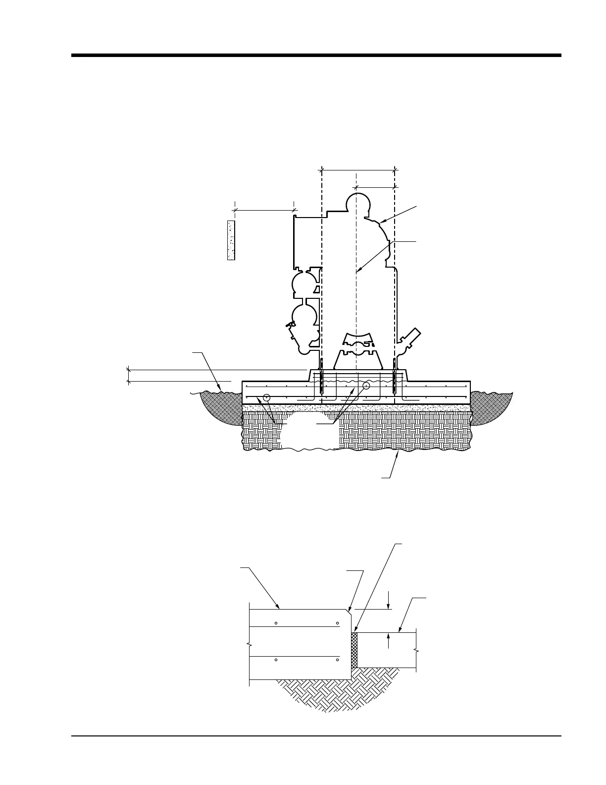
CONCRETE
SLAB IN
BUILDING
CHAMFER EDGE
COMPRESSOR UNIT
FOUNDATION
ISOLATION JOINT,
1" MINIMUM
THICKNESS
6”
Figure 3-4. Interior Foundation Isolation
Leveling and Grouting
The unit should be level in all directions. Wet the con-
crete pad according to the grout manufacturer’s direc-
tions. Mix a sufcient amount of grout. The grout must
be an expanding grout rather than shrinking to provide
a tighter bond. Follow the manufacturer’s recommenda-
tions for setting, precautions, mixing, and grout place-
ment, nishing and curing. The grout must be worked
under all areas of the feet with no bubbles or voids. If the
grout is settled with a slight outside slope, oil and water
can run off of the base. Once the grout has cured, torque
the anchor bolts as per HILTI instructions.
Figure 3-3. Concrete Pad with Compressor Unit Dimensions - Front View
CENTER LINE OF
GAS COMPRESSION
SYSTEM
6"
# 6 @ 12"
EACH WAY
TOP & BOTTOM
COMPRESSOR UNIT
G.A.
G.A.
EL. TOP OF
GRADE
EXCAVATE TO FROST DEPTH AS REQ'D AND BACKFILL
WITH CLSM OR NON-FROST SUSCEPTIBLE FILL
G.A.
CLEARANCE FROM
OBSTRUCTIONS AND
ELECTRICAL CONTROLLER
EQUIPMENT