2 – 2
VSS/VSM/VSH/VSSH • Installation, Operation and Maintenance Manual • Emerson • 35391SD
Section 2 • Theory of Operation
information on thermosyphon oil cooling, refer to Oil
Cooling - Thermosyphon Oil Cooling.
Furthermore, to collect oil from the coalescing side of
the oil separator (1), an oil return line (8) is installed be-
tween the oil separator and the compressor (9). By open-
ing the needle valve (7), this will allow oil dripping off the
coalescing lters to be fed back to the compressor.
This is a continuous cycle.
Oil Cooling
There are different methods of oil cooling for Vilter
TM
re-
frigeration compressor units. Oil cooling will depend on
the type of application, below is an explanation of each
method.
Water Cooled Oil Cooling
• In lieu of the three way oil temperature valve to con-
trol the temperature of the oil used for lubrication
and cooling of the compressor, it is required to install
a water regulating valve and solenoid valve combina-
tion to control the water supply to the oil cooler. The
water inlet connection should be made on the bot-
tom and the outlet connection on the top. The water
supply is controlled by the water regulating valve to
maintain the oil temperature at approximately 120°F.
The solenoid valve provides positive water shutoff
when the compressor is not in operation. A tempera-
ture of 150°F is considered high in most circumstanc-
es and the compressor is protected by a safety con-
trol to prevent operation of the compressor above
this temperature. Unless otherwise specied, the oil
cooler is sized for an 85°F water inlet temperature
and 10°F temperature rise.
Liquid Injection Oil Cooling
• This type of oil cooling system is designed to main-
tain compressor discharge gas temperature within
acceptable limits. Cooling is accomplished via injec-
tion of the liquid refrigerant into the compressor. For
this purpose, a liquid injection control valve station
is supplied and installed on the compressor unit.
On this valve station is an electronically controlled
motorized actuator valve assembly that controls
the ow of liquid refrigerant being injected into the
compressor.
• For additional information, refer to Section 5.
• Liquid injection cooling on booster compressors is
handled in the following manner. Using high pressure
liquid, the point of injection can be the discharge line
and no horsepower penalty is paid by injecting liquid
into the compressor discharge line. The high pressure
gas source normally used for the pressure regulator
would be compressor discharge pressure. Since, on a
booster unit, this intermediate pressure is very rarely
as high as the nominal setting of 70 psig, high stage
discharge gas is used. On high stage compressors,
the liquid is injected directly into the compressor.
However, there is a horsepower penalty when the
liquid is injected into the compressor. This will vary
with refrigerant and operating condition. The liquid
is injected into the compressor at a point in the com-
pressor cycle that minimizes the brake horsepower
penalty.
V-Plus Oil Cooling
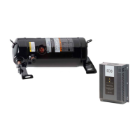
• This system consists of a liquid pump, shut-off valves,
motor, solid state variable speed controller and solid
state temperature controller. This method of oil cool-
ing is not available on the VSM compressor units. The
pump and solenoid valve cycle on and off in parallel
with the compressor drive motor. The temperature
controller receives a temperature signal from the
sensor located in the discharge and oil lines and in
turn, sends a signal to the motor speed controller.
• As the oil and de-superheating load varies, the tem-
perature controller adjusts the speed of the pump/
motor combination to maintain a constant oil
temperature.
• For additional V-Plus information, refer to
V-Plus AC Drive manual (35391XA).
Thermosyphon Oil Cooling
• Using a brazed plate or one pass shell and tube type
vessel, similar to the water cooled oil cooler, oil is
circulated on the shell side and liquid refrigerant
from the receiver is circulated through the tubes.
Thermosyphon systems use a 3-way temperature
sensing control valve to regulate oil at 120°F. Oil is
bypassed around the thermosyphon oil cooler. When
oil is higher than 120°F, the oil is passed through the
thermosyphon oil cooler. A 1/4” tubing line with
valve adds high pressure gas to the oil to quiet the
sound of injection. Open this valve in small amounts,
until noise subsides. The closed type cooling circuit is
free from the fouling problems associated with open
circuit water cooling. Since the oil cooling load is re-
jected in the condenser, this type of cooling is prac-
tical. The temperature limits here are the same as
those regarding the water cooled oil coolers.
 Loading...
