5 – 25
Section 5 • Maintenance/Service
VSS/VSM/VSH/VSSH • Installation, Operation and Maintenance Manual • Emerson • 35391SD
15. Tighten bolt and draw hub up shaft to a stop.
16. If locking tab is being used, bend locking tabs in
gap towards shaft and around bolt.
17. Install set screw in hub cap to secure key in keyway
of shaft.
18. Tighten set screw, see Table 5-5.
Drive Center Member Installation and
Alignment
NOTE
Always adjust motor to the compressor. The
compressor is aligned to the frame.
19. Adjust motor position as needed to obtain a dis-
tance of 5” between both hub faces.
20. Soft Foot. The motor must sit at on its base
(+/- 0.002”). Any soft foot must be corrected prior
to center member installation.
NOTE
If the driver or driven equipment alignment
specication is tighter than these recommendations,
the specication should be used. Also, be sure
to compensate for thermal movement in the
equipment. The coupling is capable of approximately
four time the above shaft alignment tolerances.
However, close alignment at installation will provide
longer service with smoother operation. The ex
disc pack is designed to an optimal thickness and is
not to be used for axial adjustments.
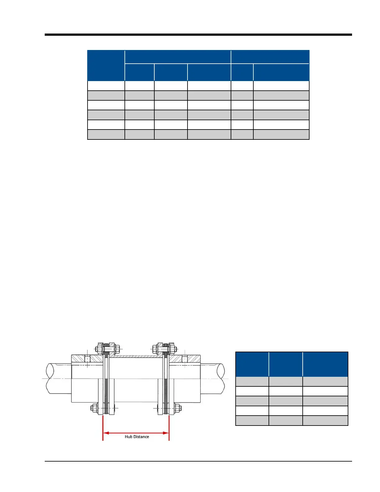
21. Axial Spacing. The axial spacing of the shafts should
be positioned so that the ex disc packs are at
when the equipment is running under normal op-
erating conditions. This means there is a minimal
amount of waviness in the ex disc pack when
viewed from the side. This will result in a ex disc
pack that is centered and parallel to its mating
ange faces. Move the motor to obtain the correct
axial spacing, see Table 5-6 and Figure 5-17.
Figure 5-17. Hub Distance (Axial Spacing)
Table 5-5. Hub Clamp Bolt and Set Screw Torque Specications
Coupling
Series/Size
Clamping Bolt Set Screw
# Bolts Size-Pitch
Torque
ft-lbs (Nm)
Size
Torque
ft-lbs (Nm)
BH38U 4 1/4-28 12 (16) 3/8 10 (13)
BH41U 4 5/16-24 23 (31) 3/8 10 (13)
BH47U 4 3/8-24 49 (66) 1/2 20 (27)
BH54U 4 7/16-20 78 (106) 1/2 20 (27)
BH56U 4 1/2-20 120 (163) 5/8 40 (54)
DP42 4 1/2-20 120 (163) 1/2 20 (27)
Coupling
Size
Lock Nut
Size
Tightening
Torque
ft-lbs (Nm)
BP38U 5/16-24 22 (30)
BP41U 7/16-20 55 (75)
BP47U 9/16-18 120 (163)
BP54U 9/16-18 120 (163)
BP56U 9/16-18 120 (163)
Table 5-6. Disc Pack Installation Torque
Specications

 Loading...


