5 – 28
Section 5 • Maintenance/Service
VSS/VSM/VSH/VSSH • Installation, Operation and Maintenance Manual • Emerson • 35391SD
9. Remove hub and key from motor shaft.
10. Loosen set screw in compressor hub securing key
in keyway.
11. Loosen clamping bolts securing hub from compres-
sor shaft.
12. Remove hub and key from compressor shaft.
Installation
13. Install key and hub on compressor shaft as noted
during removal.
14. Install set screw in compressor hub to secure key in
keyway, see Table 5-7.
15. Install clamping bolts to secure hub on compressor
shaft. Tighten clamping bolts, see Table 5-7.
16. Install key and hub on motor shaft as noted during
removal. Allow gap to install coupling sleeve.
17. Install coupling sleeve on hubs. Position hub on
motor shaft on coupling sleeve as noted during
removal.
18. Install set screw in compressor hub to secure key in
keyway. Tighten set screw, see Table 5-7.
19. Install clamping bolts to secure hub to motor shaft.
Tighten clamping bolts, see Table 5-7.
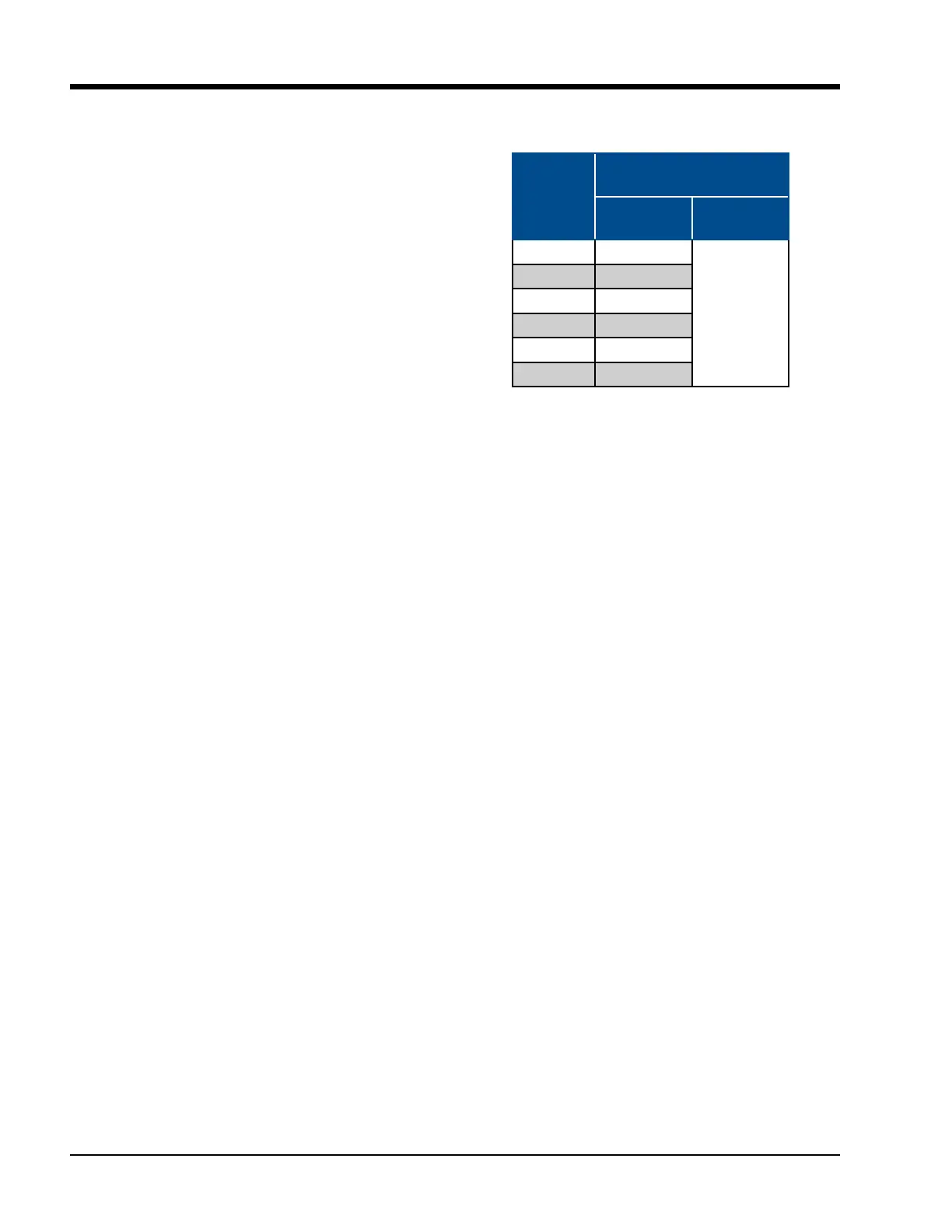
Coupling
Size
Type C
ft-lbs (Nm)
Clamping
Bolts
Key Set
Screw
6 13 (18)
13 (18)
7 13 (18)
8 23 (31)
9 23 (31)
10 50 (68)
11 50 (68)
Table 5-7. Clamping Bolts and Set
Screw Torque Specications

 Loading...


