• Typical switching point @ 1.4 mA, for secure operation:
o i=0 to 0.5 mA -> opto OFF
o i=2.5 to 30 mA -> opto ON
o imax= 30 mA
• Direct connection to a TTL/CMOS signal possible (Pin opto - to GND and pin
opto + to the TTL/CMOS signal.
Typical switching point @ 1.6 Volts, for secure operation:
o Vin< 0.8 Volts -> opto OFF
o Vin> 2.2 Volts @ 2 mA -> opto ON
o Vin max (without external resistor) = 15 Volts
4 X CMOS input/output:
•
each pin can be individually configured as an output or an input
• internal 4K7 pull up to +5V
• low level Vi<1.5 Volt (U12=74HC245)
• high level Vi>3.5 Volt (U12=74HC245)
• optional TTL compatible level (U12=74HCT245)
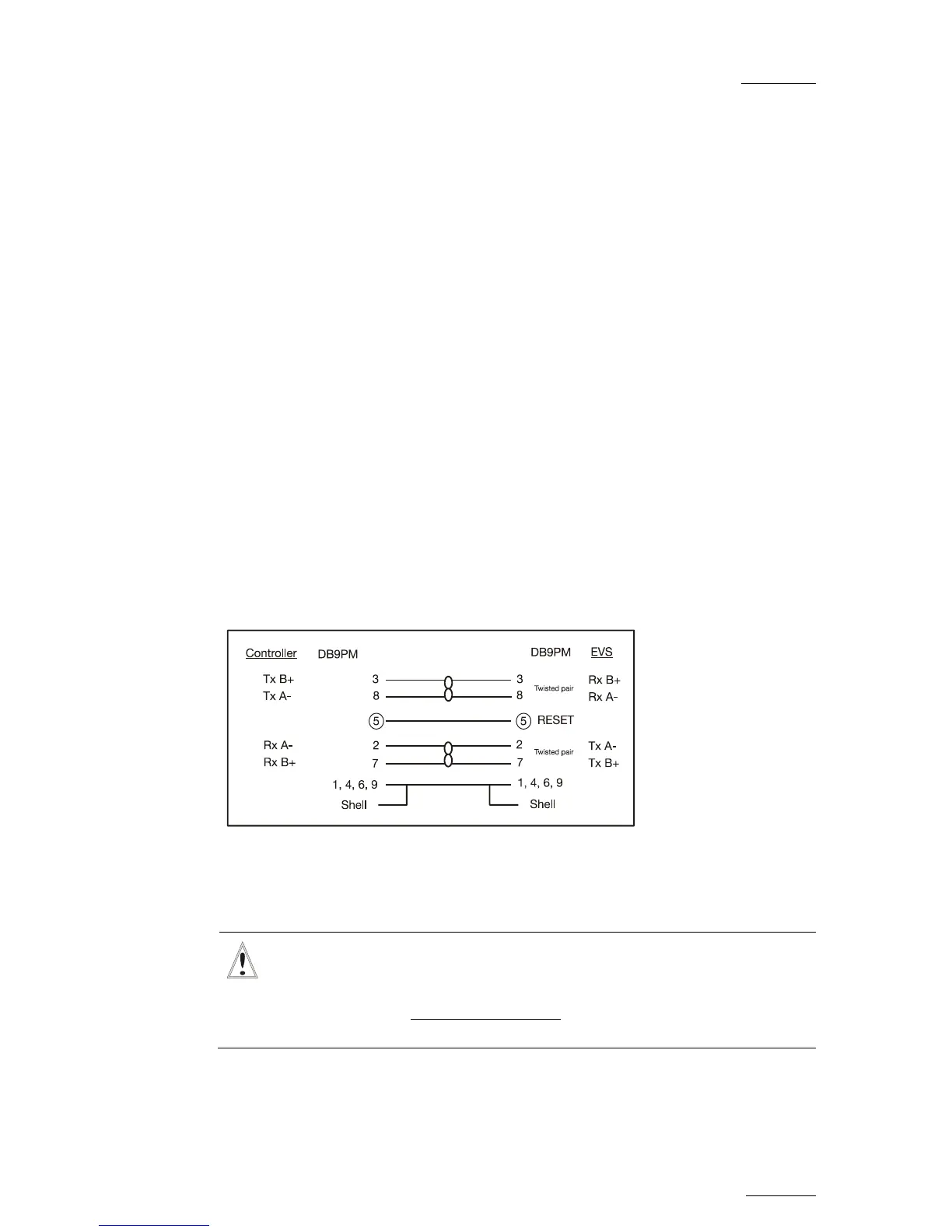
2.5 RS422 CONNECTOR
The RS 422 cable must be wired PIN TO PIN following the above diagram. Use
shielded cable to avoid electromagnetic interference on long distances.
Important
The Reset command from the Remote is sent through the Pin n°5 of
RS422 connector. This function should be disabled when the controller
on RS422 #1 is not an EVS controller
(refer to the section ‘MTPC Board’
on page 74 of this manual).
 Loading...

![Preview: EVS XT[2]](https://data.easymanua.ls/products/617905/200x200/evs-xt-2.webp)


