TF (transfer)
Blinks green while data transfers occur between the COD module and the
HCTX board
M1, M2, M3, M4 not yet used
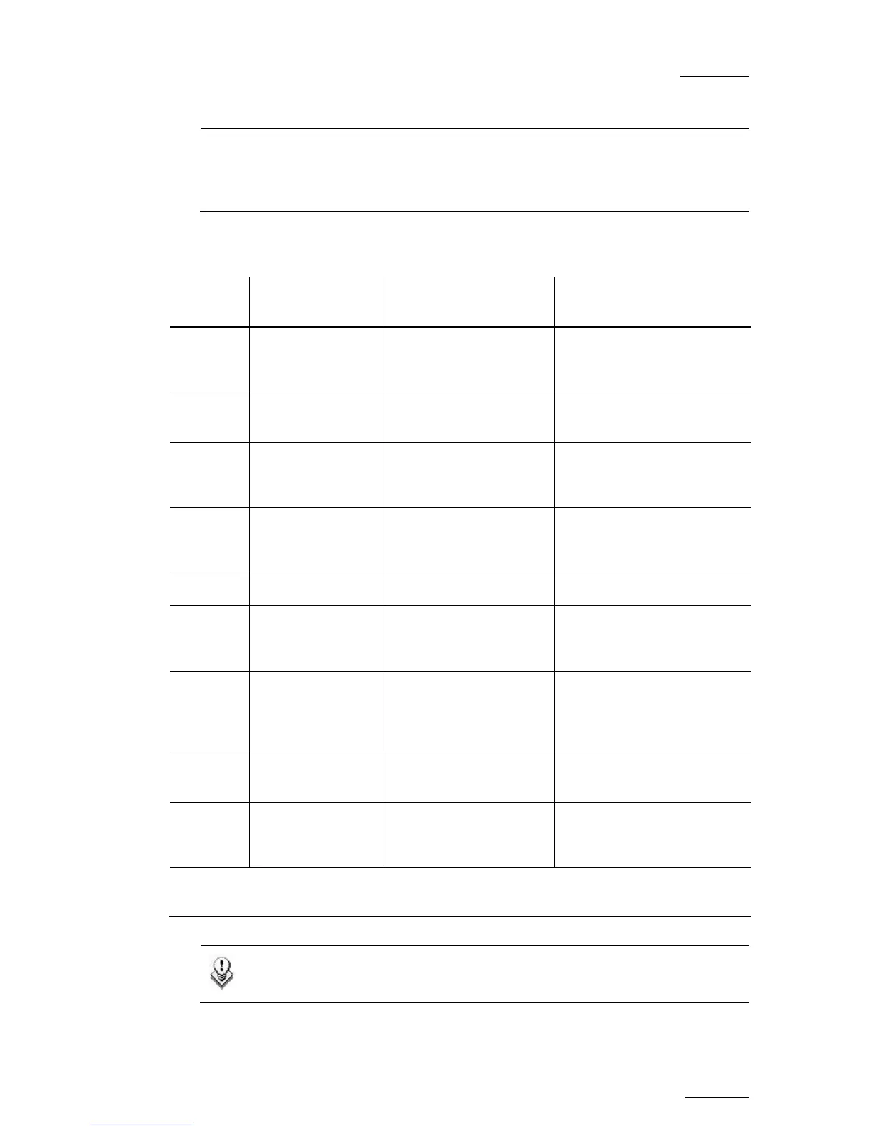
CONNECTORS ON THE COD A AND COD B MODULES
Connector SD mode HD mode
Connector label on rear
panel
J1
SDI/CVBS (*)
monitoring output
(SD)
SDI/CVBS(*) monitoring
output (SD, down-
converted) Character Outs, CVBS/SDI
J2
SDI monitoring
output (SD)
SDI monitoring output
(SD, down-converted) Used for multiviewer input
J3
Loop-through for
the SDI input
signal (SD)
SDI program output
(SD, down-converted) SD Out
J4
SDI monitoring
output (SD)
HD SDI monitoring
output
(HD) Character Outs, SD/HD
J5 Not installed Not installed n.a.
J6
SDI program
output
(SD)
HD SDI program output
(HD) SD/HD Out
J7
SDI program
output
(SD, identical to
J6)
HD SDI program output
(HD, identical to J6) SD/HD Out
J8
SDI input
(SD)
HD SDI input
(HD) SD/HD In
J9
Alternate SDI input
(SD, for hardware
loop)
Alternate HD SDI input
(HD, for hardware loop) Used for loop in
(*) The switch between SDI and CVBS on J1 is done by a software setting in the EVS
Configuration menu.
Note
The loops of the input signal are not genlocked.
 Loading...

![Preview: EVS XT[2]](https://data.easymanua.ls/products/617905/200x200/evs-xt-2.webp)


