Instruction Manual
D103409X012
Maintenance and Troubleshooting
May 2013
103
W9328
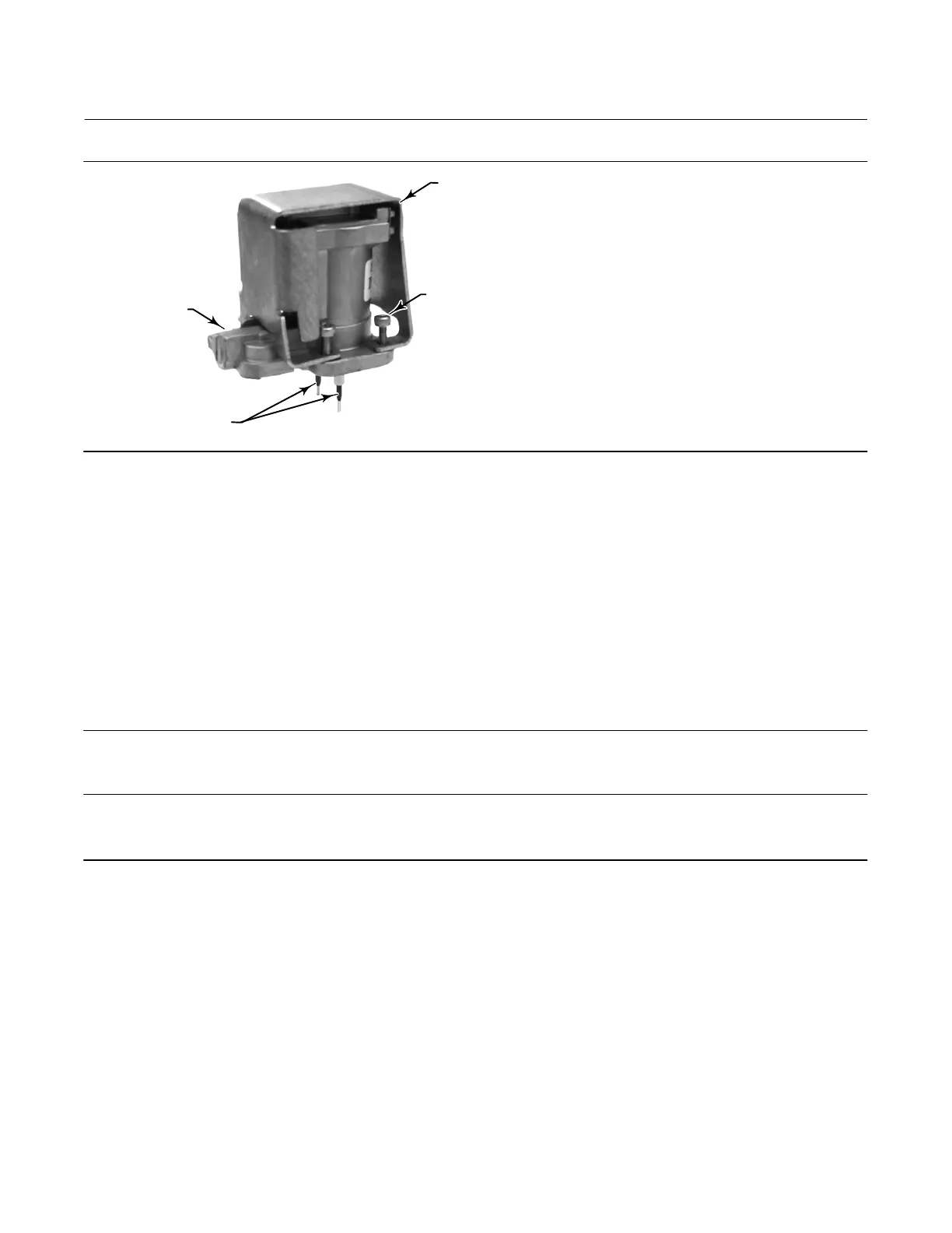
SOCKET‐HEAD
SCREWS (4)
(KEY 23)
SHROUD
(KEY 169)
I/P CONVERTER
(KEY 41)
BOOTS
(KEY 210)
Figure 7‐4. I/P Converter
3. Install the I/P converter (key 41) straight into the module base (key 2), taking care that the two electrical leads feed
into the guides in the module base. These guides route the leads to the printed wiring board assembly submodule.
4. Install the shroud (key 169) over the I/P converter (key 41).
5. Install the four socket‐head screws (key 23) and evenly tighten them in a crisscross pattern to a final torque of 1.6
NSm (14 lbfSin).
6. After replacing the I/P converter, calibrate travel or perform touch‐up calibration to maintain accuracy
specifications.
Printed Wiring Board (PWB) Assembly
Refer to figure 8‐2 or 8‐4 for key number locations. The PWB assembly (key 50) is located on the back of the module
base assembly (key 2).
Note
The PWB assembly must be firmware revision 9 or later.
Note
If the PWB assembly submodule is replaced, calibrate and configure the digital valve controller to maintain accuracy specifications.
Removing the Printed Wiring Board Assembly
1. Separate the module base from the housing by performing the Removing the Module Base procedure.
2. Remove three screws (key 33).
3. Lift the PWB assembly (key 50) straight out of the module base (key 2).
4. Ensure that the O‐rings (key 40) remain in the pressure sensor bosses on the module base assembly (key 2) after the
PWB assembly (key 50) has been removed.
Replacing the Printed Wiring Board Assembly and Setting the DIP Switch
1. Apply silicone lubricant to the pressure sensor O‐rings (key 40) and install them on the pressure sensor bosses in the
module base assembly.

 Loading...


