Instruction Manual
D103409X012
Field Communicator Menu Trees
May 2013
128
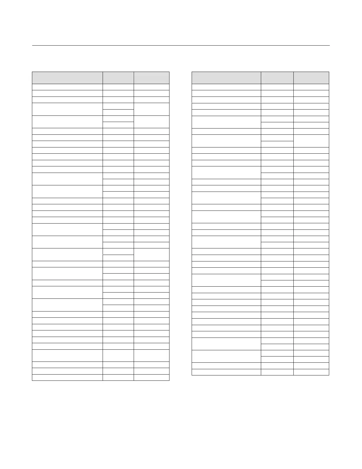
Instrument Level HC, AD, PD, and ODV
Function/Variable
Fast‐Key
Sequence
Coordinates
(1)
A minus B 3‐5‐3 4‐G
Actuator Style 1‐2‐6‐4 3‐D
Alert Conditions 2‐1 2‐F
Alert Record Full Enable
1‐2‐3‐6‐1
10‐H
1‐2‐3‐7‐1
Alert Record has Entries Enable
1‐2‐3‐6‐2
10‐H
1‐2‐3‐7‐2
Analog Input 3‐1 2‐G
Analog Input Calibration 1‐3‐2‐2 4‐E
Analog Input Range Hi 1‐2‐5‐3‐1 6‐H
Analog Input Range Lo 1‐2‐5‐3‐2 6‐H
Analog Input Units 1‐2‐5‐2‐3 6‐G
Auto Calibration 1‐3‐1‐1 4‐E
Autocalibration in Progress Enable 1‐2‐4‐2‐2 8‐H
Auxiliary Input
3‐6‐1 4‐H
1‐2‐3‐3‐1‐2 12‐D
Auxiliary Terminal Action
1‐2‐3‐3‐1‐3 12‐D
1‐2‐5‐7 4‐G
Auxiliary Terminal Alert Enable 1‐2‐3‐3‐1‐1 12‐D
Burst Command 1‐2‐1‐4‐3 6‐B
Burst Enable 1‐2‐1‐4‐1 6‐B
Calibration in Progress Enable 1‐2‐4‐2‐1 8‐H
Change Cutoffs
1-2-3-4-7-5 12-G
1-2-2-2-2-3 10-C
Change Travel Limits
1-2-3-4-7-8 12-G
1-2-2-2-2-6 10-C
Clear ALL Records
1‐2‐3‐6‐4
10‐H
1‐2‐3‐7‐4
Command 3 Configured Pressure 1‐2‐1‐4‐3 5‐A
Control Mode
Hot Key‐2 1‐A
1‐2‐1‐2 4‐B
Critical NVM Shutdown 1‐2‐3‐1‐3‐4 12‐C
Cutoff Hi
1‐2‐3‐4‐7‐3 12‐F
1‐2‐2‐2‐2‐1 10‐B
Cutoff Lo
1‐2‐3‐4‐7‐4 10‐F
1‐2‐2‐2‐2‐2 10‐B
Custom Characteriztion Table 1‐2‐2‐4 4‐C
Cycle Counter 1‐2‐3‐5‐1‐2 12‐H
Cycle Counter 3‐6‐5 4‐H
Cycle Count Alert Enable 1‐2‐3‐5‐1‐1 12‐H
Cycle Count Alert Point 1‐2‐3‐5‐1‐3 12‐H
Date 1‐2‐5‐1‐4 6‐G
Dead Band (Cycle Count / Travel
Accumulator)
1‐2‐3‐5‐3‐1 12‐H
Descriptor 1‐2‐5‐1‐3 6‐F
Device Description Information 3‐8 2‐G
Device ID 3‐7‐2 2‐H
Function/Variable
Fast‐Key
Sequence
Coordinates
(1)
Device Revision 3‐7‐5 2‐H
Diagnostic Data Available Enable 1‐2‐4‐2‐4 8‐H
Diagnostic in Progress Enable 1‐2‐4‐2‐3 8‐H
Drive Current Shutdown 1‐2‐3‐1‐1 8‐D
Drive Signal Alert Enable 1‐2‐3‐1‐2‐1 10‐D
Drive Signal
3‐4 2‐G
1‐2‐3‐1‐2‐2 10‐D
End Point Control Enable
(3)
1‐2‐2‐2‐4‐1 8‐D
Failure Group Enable
1‐2‐3‐6‐5‐1
10‐I
1‐2‐3‐7‐5‐1
Firmware Revision 3‐7‐6 2‐H
Flash ROM Shutdown 1‐2‐3‐1‐3‐5 12‐C
Hardware Revision 3‐7‐7 2‐H
HART Tag
1‐2‐5‐1‐1 6‐F
3‐7‐1 2‐H
HART Universal Revision 3‐7‐9 2‐H
Input Characterization 1‐2‐2‐3 4‐C
Instrument Date and Time
1‐2‐4‐1‐2 8‐G
1‐2‐5‐8 4‐G
Instrument Level 3‐7‐8 2‐H
Instrument Mode
Hot Key‐1 1‐A
1‐2‐1‐1 4‐B
Instrument Serial Number 1‐2‐5‐1‐6 6‐G
Instrument Time Invalid Enable 1‐2‐4‐1‐1 8‐G
Integral Dead Zone
1‐2‐4‐4‐4 8‐I
1‐2‐2‐1‐2‐1 8‐B
Integral Enable (Pressure) 1‐2‐2‐1‐3‐2 8‐C
Integral Enable (Travel) 1‐2‐2‐1‐1‐2 8‐A
Integral Gain (Pressure) 1‐2‐2‐1‐3‐3 8‐C
Integral Gain (Travel) 1‐2‐2‐1‐1‐3 8‐A
Integral Limit
1‐2‐4‐4‐3 8‐I
1‐2‐2‐1‐2‐2 8‐B
Integrator Saturated Hi Enable 1‐2‐4‐4‐1 8‐I
Integrator Saturated Lo Enable 1‐2‐4‐4‐2 8‐I
Last AutoCal Status 1‐2‐5‐9‐1 6‐H
Last Calibration Type 1‐2‐5‐9‐2 6‐H
Lead/Lag
(3)
1‐2‐2‐5‐3 5‐D
Loop Current Validation Enable
(2)
1‐2‐3‐3‐3 9‐E
Low Power Write Fail Enable 1‐2‐3‐1‐3‐2 12‐B
Manual Calibration 1‐3‐1‐2 4‐E
Manufacturer
3‐7‐3 2‐H
1‐2‐6‐1 3‐D
Maximum Recorded Temperature
2‐3‐1 3‐F
3‐6‐3 4‐H
Maximum Supply Pressure 1‐2‐5‐6 4‐G
Message 1‐2‐5‐1‐2 6‐F
NOTE: Italicized Fast‐Key Sequence indicates fast‐key sequence is applicable only for instrument level ODV.
1. Coordinates are to help locate the item on the menu tree on page 130 and 131.
2. Instrument level AD, PD, and ODV only.
3. Instrument level ODV only.
4. Instrument level HC, AD, and PD only.
5. Instrument level HC only.

 Loading...


