Instruction Manual
D103409X012
Installation
May 2013
16
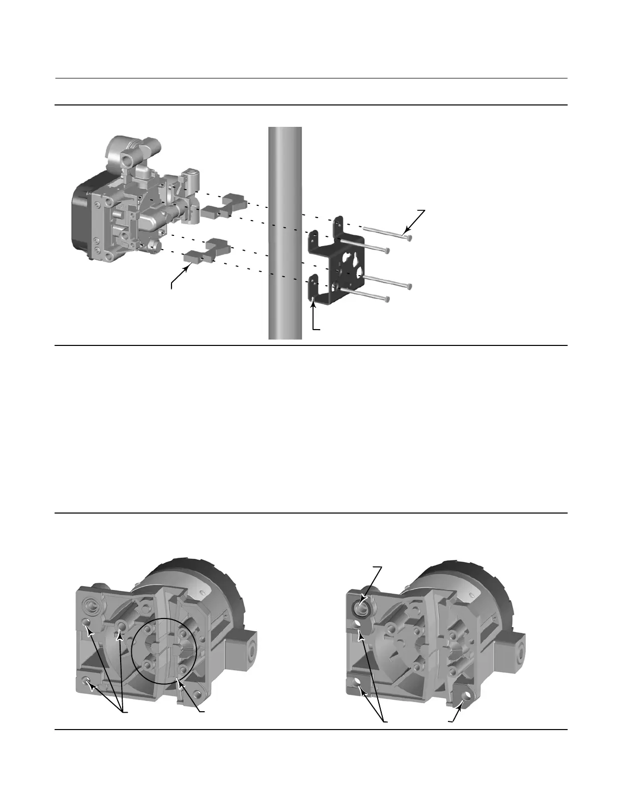
Figure 2‐6. FIELDVUE DVC6205 Base Unit Pipestand Mounting
4‐INCH 1/4‐20
HEX HEAD SCREW
STANDOFF
MOUNTING BRACKET
X0437
Mounting the DVC6215 Feedback Unit
If ordered as part of a control valve assembly, the factory mounts the feedback unit on the actuator, makes pneumatic
connections to the actuator, sets up, and calibrates the instrument. If you purchased the feedback unit separately, you
will need a mounting kit to mount the feedback unit on the actuator. See the instructions that come with the
mounting kit for detailed information on mounting the feedback unit to a specific actuator model.
The DVC6215 housing is available in two different configurations, depending on the actuator mounting method.
Figure 2‐7 shows the available configurations. The feedback system for the DVC6215 feedback unit utilizes a magnetic
assembly for true linkage‐less, non‐contacting position measurement. In order to prevent inadvertent stem
movement while the instrument is in operation, magnetic tools (such as a magnetic‐tipped screwdriver) should not be
used.
Figure 2‐7. Feedback Unit Housing Configurations
LINEAR, M8
ROTARY NAMUR, M6
HOUSING FOR
LINEAR AND ROTARY ACTUATORS
HOUSING FOR
FISHER GX ACTUATORS
HOLES FOR
MOUNTING BOLT
X0125
X0124
INTEGRAL OUTPUT
PRESSURE PORT

 Loading...


