Instruction Manual
D103409X012
Parts
May 2013
115
Key Description Part Number
I/P Converter Assembly
(see figure 8‐2 and 8‐4)
DVC6200 and DVC6205
23 Cap Screw, hex socket, SST
(2)(8)
(4 req'd)
39* O‐ring
(1)(3)(5)
41 I/P Converter
(5)
169 Shroud
(5)(8)
(see figure 7‐4)
210* Boot, nitrile
(1)(5)
(2 req'd) (see figure 7‐4)
231* Seal Screen
(1)(3)(5)
Relay (see figure 8‐2 and 8‐4)
DVC6200 and DVC6205
24* Relay Assembly, (includes shroud, relay seal, mounting screws)
Standard (nitrile elastomers)
Standard Bleed
Housing A (used for GX actuator)
Single‐/acting direct (relay C) 38B5786X182
Single‐acting reverse (relay B) 38B5786X172
Housing B (used for all actuators except GX)
Single‐acting direct (relay C) 38B5786X132
Double‐acting (relay A) 38B5786X052
Single‐acting reverse (relay B) 38B5786X092
Low Bleed
Housing A (used for GX actuator)
Single‐acting direct (relay C) 38B5786X202
Single‐acting reverse (relay B) 38B5786X192
Housing B (used for all actuators except G)
Single‐acting direct (relay C) 38B5786X152
Double‐acting (relay A) 38B5786X072
Single‐acting reverse (relay B) 38B5786X112
Extreme Temperature option (fluorosilicone elastomers)
Standard Bleed
Single‐acting direct (relay C) 38B5786X142
Double‐acting (relay A) 38B5786X032
Single‐acting reverse (relay B) 38B5786X102
Low Bleed
Single‐acting direct (relay C) 38B5786X162
Double‐acting (relay A) 38B5786X082
Single‐acting reverse (relay B) 38B5786X122
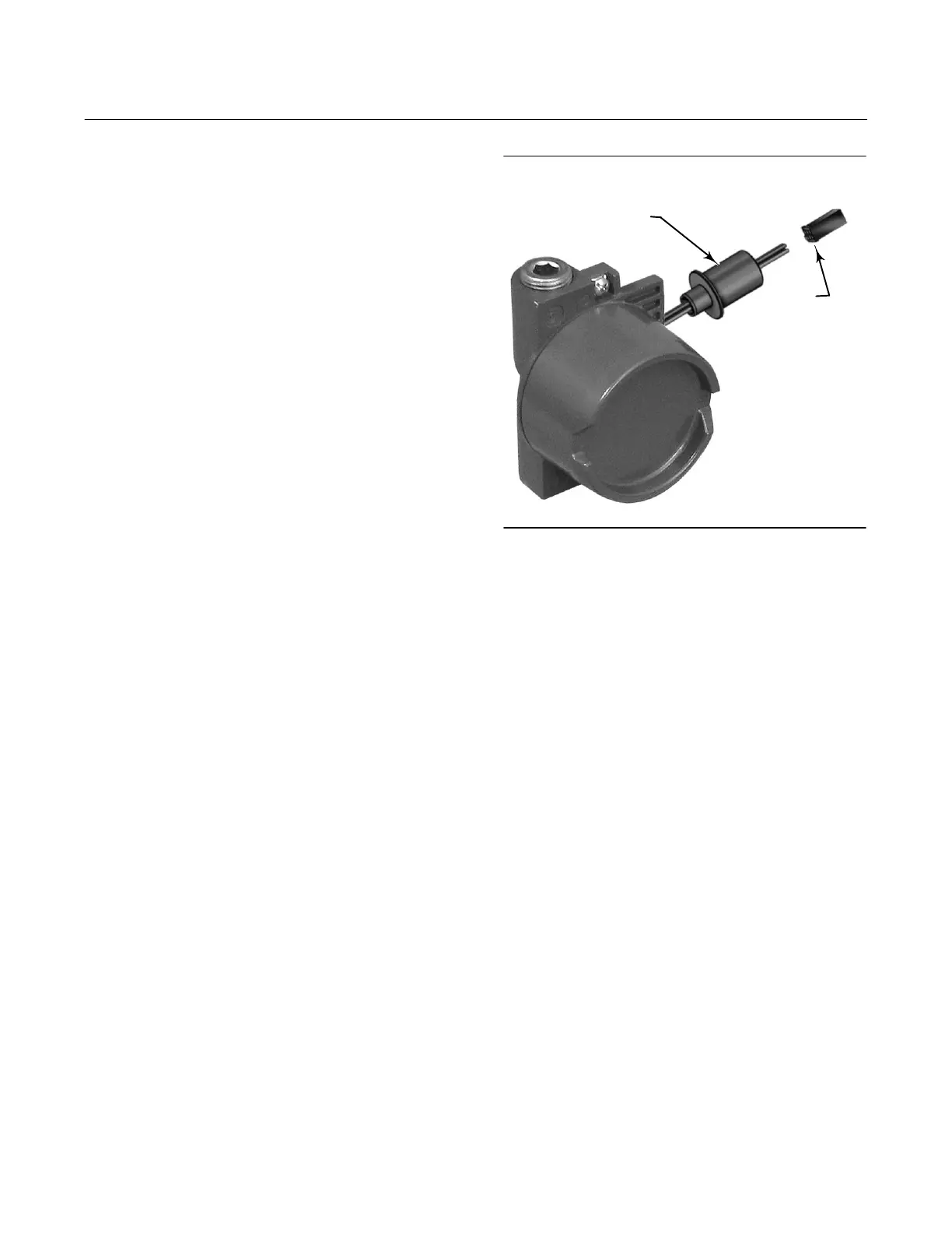
Figure 8‐1. Terminal Box of Natural Gas Certified
FIELDVUE DVC6200 Digital Valve Controller
GAS‐BLOCKING
PRESS‐FIT ADAPTOR
WIRING
CONNECTOR
W9922
Key Description Part Number
Loop Connections Terminal Box
(see figure 8‐2 and 8‐4)
DVC6200 and DVC6205
4 Terminal Box Cap
34* O‐ring
(1)(4)
36* O‐ring
(1)(4)
58 Set Screw, hex socket, SST
(2)
72 Cap Screw, hex socket, SST
(2)
164 Terminal Box Assembly
Feedback Connections Terminal
Box (see figure 8‐4)
DVC6205
4 Terminal Box Cap
34* O‐ring
(1)(4)
36* O‐ring
(1)(4)
58 Set Screw, hex socket, SST
(2)
62 Pipe Plug, hex hd, SST
262 Adapter
263* O-ring
Standard 1F463606992
Extreme temperature option, (fluorosilicone) 1F4636X0092
*Recommended spare parts
1. Available in the Elastomer Spare Parts Kit
2. Available in the Small Hardware Spare Parts Kit
3. Available in the Seal Screen Kit
4. Available in the Terminal Box Kit
5. Available in the I/P Converter Kit
8. Available in the Spare Shroud Kit

 Loading...


