Instruction Manual
D103409X012
Calibration
May 2013
78
Travel Calibration
Field Communicator Configure > Calibrate > Travel Calibration (1‐3‐1)
If a double‐acting relay is used, you will be prompted to run the relay adjustment when auto or manual calibration is
selected. Select Yes to adjust the relay, select No to proceed with calibration. For additional information, refer to Relay
Adjustment in this section.
Note
Relay Adjustment is only available for the double‐acting relay (Relay A).
Auto Travel Calibration
1. The auto calibration procedure is automatic. It is completed when the Calibrate menu appears.
During calibration, the instrument seeks the high and low end points and the minor loop feedback (MLFB) and output
bias. By searching for the end points, the instrument establishes the limits of physical travel, i.e. the actual travel 0 and
100% positions. This also determines how far the relay beam swings to calibrate the sensitivity of the MLFB sensor.
2. Place the instrument In Service and verify that the travel properly tracks the current source.
If the unit does not calibrate, refer to table 5‐1 for error messages and possible remedies.
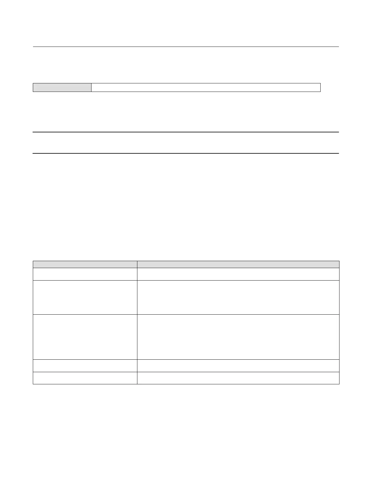
Table 5‐1. Auto Calibrate Travel Error Messages
Error Message Possible Problem and Remedy
Power failure occurred during Auto Calib
The analog input signal to the instrument must be greater than 3.8 mA. Adjust the current output
from the control system or the current source to provide at least 4.0 mA.
Auto Calib did not complete within the time limit.
The problem may be one or the other of the following:
1. The tuning set selected is too low and the valve does not reach an end point in the allotted time.
Press the Hot Key, select Stabilize/Optimize then Increase Response (selects next higher tuning set).
2. The tuning set selected is too high, valve operation is unstable and does not stay at an end point
for the allotted time. Press the Hot Key, select Stabilize/Optimize then Decrease Response (selects next
lower tuning set).
Insufficient travel
Prior to receiving this message, did the instrument output go from zero to full supply? If not, verify
instrument supply pressure by referring to the specifications in the appropriate actuator instruction
manual. If supply pressure is correct, check instrument pneumatic components (I/P converter and
relay).
If the instrument output did go from zero to full supply prior to receiving this message, then verify
proper mounting by referring to the appropriate mounting procedure in the Installation section and
checking the magnet array for proper alighment.
Drive signal exceed low limit; check supply
pressure
1. Check supply pressure (reverse‐acting relay)
2. Friction is too high.
Drive signal exceed high limit; check supply
pressure
1. Check supply pressure (direct‐acting relay)
2. Friction is too high

 Loading...


