Instruction Manual
D103409X012
Field Communicator Menu Trees
May 2013
129
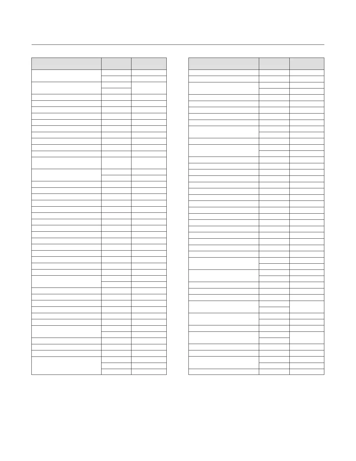
Function/Variable
Fast‐Key
Sequence
Coordinates
(1)
Minimum Recorded Temperature
2‐3‐2 3‐F
3‐6‐4 4‐H
Miscellaneous Group Enable
1‐2‐3‐6‐5‐3
10‐I
1‐2‐3‐7‐5‐3
Model 3‐7‐4 2‐H
Multi‐Drop Alert Enable 1‐2‐4‐3‐2 8‐H
Non‐Critical NVM Alert Enable 1‐2‐3‐1‐3‐3 12‐C
Number of Power Ups 2‐3‐4 4‐G
Number of Power Ups 3‐6‐9 4‐H
Offline/Failed Alert Enable 1‐2‐3‐1‐3‐1 12‐B
Partial Stroke Test
(3)
2‐5 2‐F
Partial Stroke Test Enable
(3)
1‐2‐7‐1 3‐D
Partial Stroke Test Pressure Limit
(3)
1‐2‐3‐6‐1 10‐G
Partial Stroke Test Start Point
(3)
1‐2‐2‐2‐5‐2 8‐D
Partial Stroke Test Variables
View/Edit
(3)
1‐2‐7‐2 3‐D
Performance Tuner
(2)
1‐1‐2 2‐B
1‐2‐2‐1‐1‐5 8‐A
Polling Address 1‐2‐5‐1‐7 6‐G
Pressure A 3‐5‐1 4‐G
Pressure B 3‐5‐2 4‐G
Pressure Control Active Enable 1‐2‐4‐3‐1 8‐H
Pressure Deviation Alert Enable
(3)
1‐2‐3‐6‐2 10‐G
Pressure Deviation Alert Point
(3)
1‐2‐3‐6‐3 10‐G
Pressure Deviation Time
(3)
1‐2‐3‐6‐4 10‐G
Pressure Range Hi 1‐2‐2‐2‐3‐1 10‐D
Pressure Range Lo 1‐2‐2‐2‐3‐2 10‐D
Pressure Sat Time
(3)
1‐2‐2‐2‐4‐4 8‐D
Pressure Sensor Shutdown
(2)
1‐2‐3‐2‐3 12‐C
Pressure Sensors—Calibration 1‐3‐2‐1 4‐E
Pressure Set Point
(3)
1‐2‐2‐2‐5‐3 8‐D
Pressure Tuning Set 1‐2‐2‐1‐3‐1 10‐B
Pressure Units 1‐2‐5‐2‐1 6‐G
Protection
Hot Key‐3 1‐A
1‐2‐1‐5 4‐B
Raw Travel Input 3‐6‐7 4‐H
Reference Voltage Shutdown 1‐2‐3‐1‐3‐7 12‐C
Relay Adjust 1‐3‐3 3‐E
Relay Type 1‐2‐5‐4 4‐F
Restart Control Mode 1‐2‐1‐3 4‐B
Restore Factory Settings 1‐3‐4 3‐E
Setpoint (Travel)
1‐2‐3‐4‐2 9‐E
3‐2 2‐G
Set Point Rate Close 1‐2‐2‐5‐2 5‐D
Set Point Rate Open 1‐2‐2‐5‐1 5‐D
Setup Wizard 1‐1‐1 2‐B
Stabilize/Optimize
Hot Key‐4 1‐A
1‐1‐2
(5)
2‐B
1‐2‐2‐1‐1‐4 8‐A
Function/Variable
Fast‐Key
Sequence
Coordinates
(1)
Status 2‐2 2‐F
Stroke Valve 2‐4 2‐F
Supply
(2)
3‐5‐4 4‐G
1‐2‐3‐3‐2‐2 12‐D
Supply Pressure Lo Alert Enable
(2)
1‐2‐3‐3‐2‐1 12‐D
Supply Pressure Lo Alert Point
(2)
1‐2‐3‐3‐2‐3 12‐D
Temperature 3‐6‐2 4‐H
Temperature Sensor Shutdown 1‐2‐3‐2‐2 12‐C
Temperature Units 1‐2‐5‐2‐2 6‐G
Travel
3‐3 2‐G
1‐2‐3‐4‐1 9‐E
Travel / Pressure Select 1‐2‐2‐2‐1 5‐C
Travel Accumulator
3‐6‐6 4‐H
1‐2‐3‐5‐3‐2 12‐H
Travel Accumulator Alert Enable 1‐2‐3‐5‐3‐1 12‐I
Travel Accumulator Alert Point 1‐2‐3‐5‐3‐3 12‐I
Travel Alert Dead Band 1‐2‐3‐4‐3 9‐E
Travel Alert Hi Enable 1‐2‐3‐4‐6‐1 10‐F
Travel Alert Hi Hi Enable 1‐2‐3‐4‐5‐1 12‐E
Travel Alert Hi Hi Point 1‐2‐3‐4‐5‐3 12‐F
Travel Alert Hi Point 1‐2‐3‐4‐6‐3 10‐F
Travel Alert Lo Enable 1‐2‐3‐4‐6‐2 10‐F
Travel Alert Lo Lo Enable 1‐2‐3‐4‐5‐2 12‐E
Travel Alert Lo Lo Point 1‐2‐3‐4‐5‐4 12‐F
Travel Alert Lo Point 1‐2‐3‐4‐6‐4 10‐F
Travel Deviation Alert Enable 1‐2‐3‐4‐4‐1 10‐E
Travel Deviation Alert Point 1‐2‐3‐4‐4‐2 10‐E
Travel Deviation Time 1‐2‐3‐4‐4‐3 10‐E
Travel Limit/Cutoff Hi Alert Enable 1‐2‐3‐4‐7‐1 12‐F
Travel Limit/Cutoff Lo Alert Enable 1‐2‐3‐4‐7‐2 12‐F
Travel Limit Hi
1‐2‐3‐4‐7‐6 12‐G
1‐2‐2‐2‐2‐4 10‐C
Travel Limit Lo
1‐2‐3‐4‐7‐7 12‐G
1‐2‐2‐2‐2-3 10‐C
Travel Sensor Motion 1‐2‐6‐5 3‐E
Travel Sensor Shutdown 1‐2‐3‐2‐1 12‐C
Travel Tuning Set 1‐2‐2‐1‐1‐1 10‐A
Valve Group Enable
1‐2‐3‐6‐5‐2
10‐I
1‐2‐3‐7‐5‐2
Valve Serial Number
1‐2‐5‐1‐5 6‐F
1‐2‐6‐2 3‐D
Valve Style 1‐2‐6‐3 3‐D
View Alert Records
1‐2‐3‐6‐3
10‐H
1‐2‐3‐7‐3
View/Edit Feedback Connection 1‐2‐6‐6 3‐E
View/Edit Lag Time
(4)
1‐2‐2‐5‐3 5‐D
View Number of Days Powered Up
2‐3‐3 3‐F
3‐6‐8 4‐I
Zero Power Condition 1‐2‐5‐5 4‐G
NOTE: Italicized Fast‐Key Sequence indicates fast‐key sequence is applicable only for instrument level ODV.
1. Coordinates are to help locate the item on the menu tree on page 130 and 131.
2. Instrument level AD, PD, and ODV only.
3. Instrument level ODV only.
4. Instrument level HC, AD, and PD only.
5. Instrument level HC only.

 Loading...


