S E T U P F O R M C H A P T E R 4
Receive Rejection
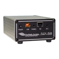
Figure 96: Receive Rejection
Image Rejection means finding adjustments for phase angle and gain differences between the left and
right channels in the in-phase (I) and quadrature (Q) signals.
Phase: Sets the phase offset between the I and Q channels. Ideally, the phase angle difference
between I and Q (right and left channels) of a tone in our passband will be 90 degrees.
Gain: Sets the amplitude offset between the I and Q channels. Ideally, the amplitude of both I
and Q (left and right) channels of a received tone will be equal.
Transmit Rejection
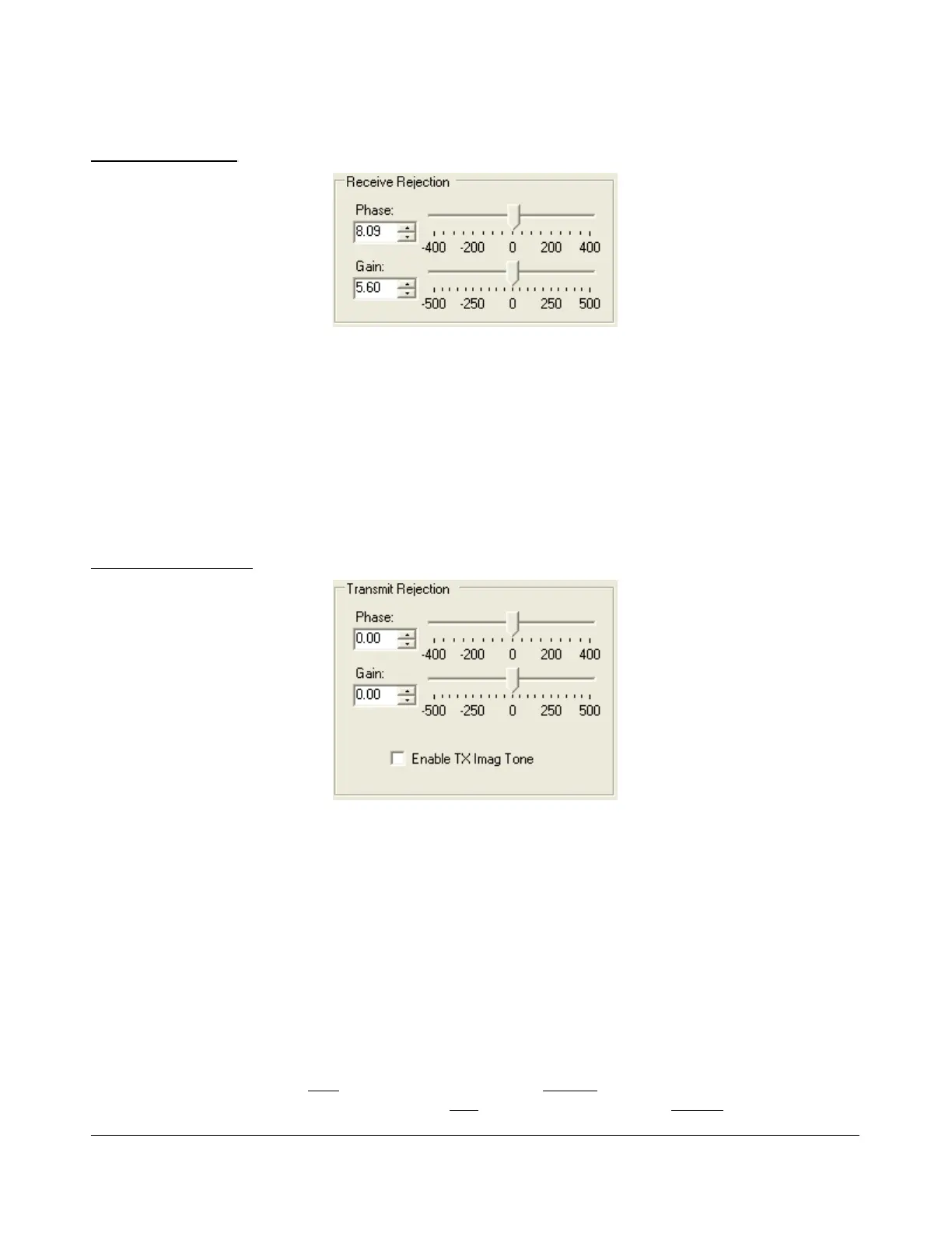
Figure 97: Transmit Rejection
Similar to above, these controls enable the user to adjust the image rejection for the transmitter. The
calibration requires external instruments. A spectrum analyzer is ideal but a second receiver should
enable you to get satisfactory rejection levels.
To minimize the transmit image, proceed as follows:
1. Set the radio to either USB or LSB. Connect the radio to a dummy load and select Enable TX
Image Tone.
2. Click MOX (front console) and a full strength tone will be transmitted at the frequency shown in
VFO A. Adjust the output power with the Drive control (front console).
3. If the radio is set to USB, look at the image signal BELOW the carrier in either the spectrum
analyzer or the second receiver. If set to LSB, look at the image signal ABOVE the carrier.
105 2003-2008 FlexRadio Systems

 Loading...