H A R D W A R E I N S T A L L A T I O N C H A P T E R 1
Location Considerations
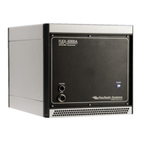
To facilitate integrating your FLEX-5000 into your shack you may want to consider the following:
Place the FLEX-5000A in close proximity to your computer . It is best to use the shortest
FireWire cable possible to connect to your computer to minimize data errors and limit possible
RFI getting into the computer. High quality, quad-shielded FireWire cables up to 10m in length
have been used successfully with the FLEX-5000.
Ensure convenient access to the back panel . The FLEX-5000 back panel is where most of your
connections will be made. Having easy access to the back panel without moving the
transceiver is optimal while getting started.
Avoid placing the FLEX-5000 in direct sunlight . Placing the transceiver in direct sunlight will
increase the ambient temperature inside the chassis (especially while transmitting) and make
the high volume cooling fan’s job more difficult.
Heed air flow requirements . Air is drawn in through the bottom air vent in the front of the
FLEX-5000 and is exhausted through the top vent in the rear for optimal cooling. Do not block
either the front intake or the rear exhaust vent since this will reduce the cooling efficiency.
Avoid contact with liquids . Although this is usually not a problem unless you are operating
maritime mobile, accidental spills of liquids in the shack on the FLEX-5000 could result in
voiding the warranty. Placing the FLEX-5000 away from food and drinks is highly
recommended.
Physical Connections
To facilitate integrating the FLEX-5000 into your station, it is worth taking a moment to study the
radio's front and back panels. The many antenna and audio connections are not immediately intuitive.
This is a direct consequence of the FLEX-5000's versatility in accommodating many configurations,
including receive-only antennas, external signal enhancing equipment and transverters, all of which can
be assigned on a per band basis, without requiring complex external switching arrangements.
We will now discuss first the front panel and then the back panel connections
1
.
Hint: You can also visit the interactive virtual tour on our website of the
FLEX-5000A front panel and back panel respectively (on our website
select Products and then Interactive Virtual Tours), where you can
hover over a connector with your mouse to pop up its description.
[The rest of this page has been left blank intentionally]
1
Identifiers refer to the same controls and connectors on the FLEX-5000A and C models.
3 2003-2008 FlexRadio Systems

 Loading...