TGA100 Rev0106
10
INSTALLATION
When the governor is programmed at the factory there will be a label on the
governor specifying the engine type. If there is no label on the governor the engine type
must be verified/programmed per the Programming procedure.
Install Control Panel
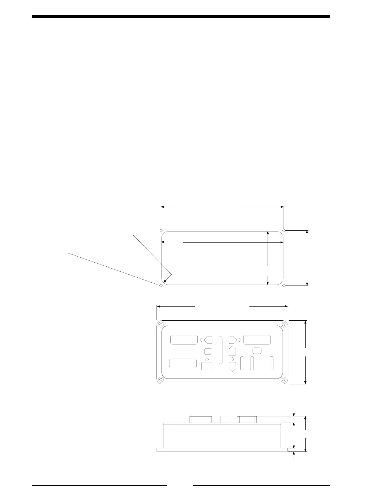
1. Measure and mark mounting location for control module panel cutout and
mounting screw holes. Make sure there is clearance behind the panel for the
module and cables before cutting holes. Refer to Figure 2 for layout and
dimensions.
2. Cut out a 9 by 3 15/16 inch hole and drill four holes for mounting screws.
3. Place control module in position and secure with four screws (10-32 mounting
hardware is recommended).
4. Connect cables at rear of the contol module. (Refer to Wiring section.)
Figure 2. Control Panel Mounting Dimensions
Panel
Cutout
Maximum
Radius 1/2"
9"
3 15/16"
9 1/16"
4 1/16"
9 11/16"
4 11/16"
2 3/4"
5/8"
1/4"
10-32 mounting
hardware is
recommended.
 Loading...