TGA100 Rev0106
22
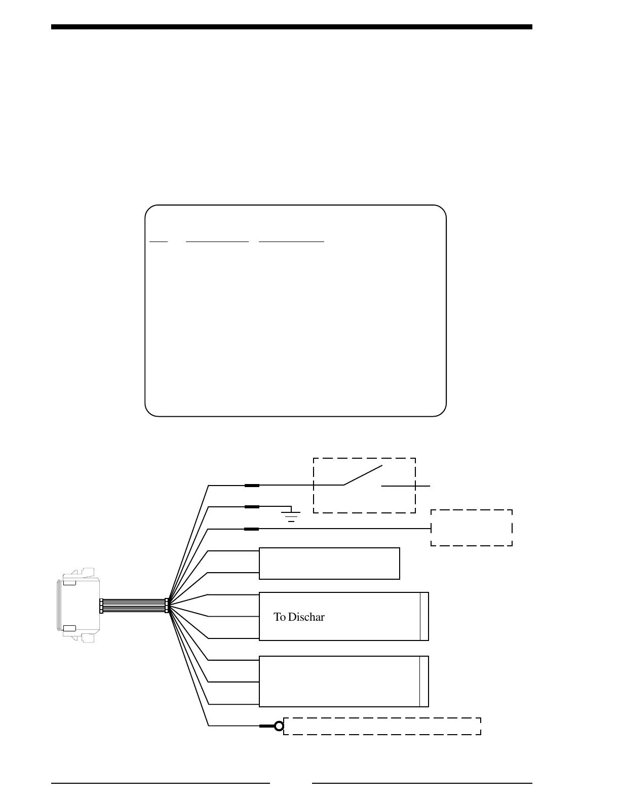
Note: The pump interlocks must be made for the governor to control the engine.
Figure 4. TGA 12-Pin Connector Wiring
WIRING
The following figures include the schematics, wiring diagrams, block diagrams,
and cables for the INControl.
Connectors and Cables
For most electronic engines, the INControl receives engine RPM, oil pressure,
and coolant temperature data over the J1587 databus from the engine ECM. Some
engines do not broadcast this data over the databus and sensors may need to be
installed.
12 Pin Connector/Cable
Pin Wire Color Description
1 Red +12 VDC Supply Voltage
2 Black Ground
3 White Interlock Input (+12 VDC)
4 Red J1587 (+)
5 Black J1587 (–)
6 Red +5 VDC Discharge Sensor
7 Black Ground Discharge Sensor
8 White Signal Discharge Sensor
9 Red +5 VDC Intake Sensor
10 Black Ground Intake Sensor
11 White Signal Intake Sensor
12 White Engine Oil Pressure Senor
12-Pin
Connector
RED
BLK
WHT
RED
BLK
RED
BLK
WHT
RED
BLK
WHT
WHT
To Discharge Pressure Sensor
To Intake Pressure Sensor
+12
VDC
Ignition Key
GND
+12 VDC
Pump Engaged
Interlock
To J1587
(See Engine Specific Wiring)
To Engine Oil Pressure Sensor if Needed
12-Pin Cable
RED
GREEN
 Loading...