TGA100 Rev0106
11
Install Pressure Sensors
The two pressure sensors are mounted on the discharge and intake manifolds of
the pump. If there is a check valve in the discharge side of the pump, mount the
discharge transducer before the check valve. T-fittings can be used to mount the pressure
transducers.
Note: Install the pressure sensor upright so water in the end of the pressure
transducer is able to drain back into the pipe.
1. Screw the sensor into a 1/4-18 NPT hole.
Caution: Do not use the main body that houses the electronics to tighten the
pressure sensor. Damage to the transducer may occur.
2. Tighten the sensor with a 9/16-inch (3/4 for alternate part) wrench on the lower
hex fitting.
3. Connect the pressure sensor cable from the control module to the pressure
sensor. (Refer to Wiring section.)
Caution: Do not use the main body
that houses the electronics to tighten
the sensor. Damage to the sensor
may occur.
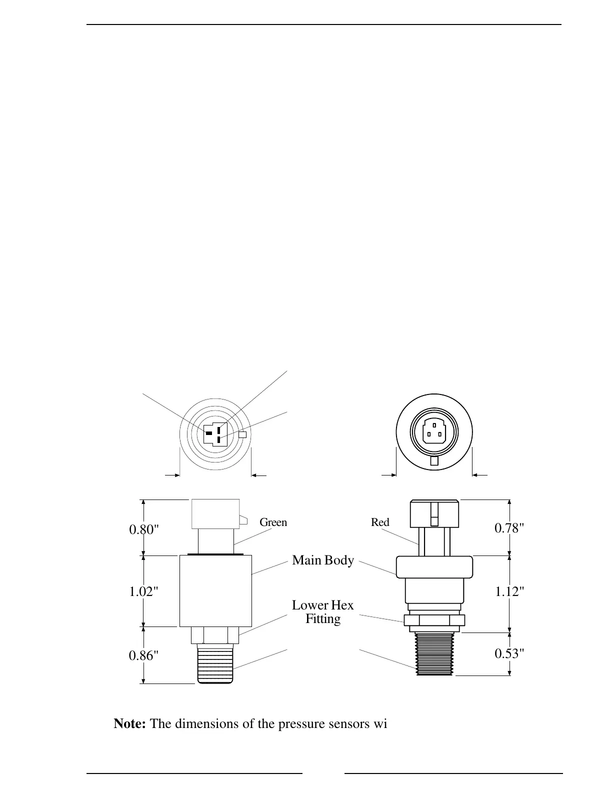
Figure 3. Pressure Sensors
Intake - XE-IO3100PT2
Discharge - XE-FP4000PT1
1/4-18 NPT
1234567890
1234567890
1234567890
1234567890
1234567890
1234567890
1234567890
1234567890
1234567890
1234567890
1234567890
Lower Hex
Fitting
Main Body
1.02"
0.86"
0.80"
0.53"
0.78"
1.12"
Green Red
Note: The dimensions of the pressure sensors will be changing on or about
01April06. (Reference PCN0601-01.)
Supply
Voltage
5 VDC
Output
Signal
Ground
1.04"
1.06"
 Loading...