4. INSTALLATION
35
Optional equipment
* WIth ACCU-FISH
TM
, bottom discrimination display support.
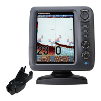
4.2 Display Unit
Mounting considerations
The display unit can be installed on a desktop,
or flush mounted in a console. When choos-
ing a location keep the following in mind:
Name Type Code No. Remarks
Transducer
520-5PSD* 000-015-204 Thru-hull mount, plastic
520-5MSD* 000-015-212 Thru-hull mount, metal
520-PLD* 000-177-684-10 Thru-hull mount, plastic
525-5PWD* 000-146-966-01 Transom mount, plastic
Triducer (trans-
ducer with speed/
temperature sen-
sor)
525T-PWD* 000-177-688-10 Transom mount, plastic
525T-BSD* 000-177-685-10 Thru-hull mount, metal
525STID-MSD* 000-011-783 Thru-hull mount, metal
525STID-PWD* 000-011-784 Transom mount, plastic
525T-LTD/12* 000-177-686-10 Tilt angle 12°, thru-hull mount, metal
525T-LTD/20* 000-177-687-10 Tilt angle 20°, thru-hull mount, metal
SS60-SLTD/12* 000-177-690-10 Tilt angle 12°, thru-hull mount, alloy
SS60-SLTD/20* 000-177-691-10 Tilt angle 20°, thru-hull mount, alloy
Converter Cable
Assy.
02S4147-1 000-141-082 Speed sensor, Speed/ Temperature sen-
sor
Cable Assy. KON-004-02M 001-090-910 2 m
Speed/ Tem-
perature Sensor
ST-02MSB 000-137-986-01 Thru-hull mount, metal
ST-02PSB 000-137-987-01 Thru-hull mount, plastic
Temperature
Sensor
T-04MSB 000-026-893 Thru-hull mount
T-04MTB 000-026-894 Transom mount
Inside Hull Kit S 22S0191-2 000-802-598 w/installation instructions, not available
with bottom discrimination display.
Matching Box MB-1100 000-041-353 For FCV-587, connection to 1 kW trans-
ducer
Transducer (for
FCV-587)
50B-6 000-015-042 10 m, 1 kW
50B-6B 000-015-043 15 m, 1 kW
200B-5S 000-015-029 10 m, 1 kW
50/200-1T* 000-015-170 10 m, 1 kW
50/200-12M* 000-015-171 10 m, 1 kW
Triducer (for
FCV-587)
526TID-HDD* 000-177-689-10 Thru-hull mount, metal, 1 kW (Not re-
quired Matching Box MB-1100.)
• Locate the unit away from the air from air
conditioners.
• The operating temperature range is 5°F to
131°F.
• Locate the unit away from devices that emit
active gas.
• The mounting location must be well ventilat-
ed.
• Select a location where vibration and shock
are minimal.
• Select a location out of direct sunlight. Pro-
longed exposure to direct sunlight can
cause LCD blackout.
• A magnetic compass will be affected if the
display unit is placed too close to the com-
pass. Observe the compass safe distances
in the safety instructions to prevent distur-
bance to the compass.
 Loading...