16. RADAR OVERLAY
16-6
6) [Heading Align]: Some positioning error may occur when the antenna unit is
installed. This error can be compensated from the ECDIS.
1) Set the chart scale on the ECDIS between 1:2,000 and 1:4,000. Select a
target echo which is near the radar heading line on the ECDIS.
2) Use the EBL control on the ECDIS to bisect the target echo.
3) Read the target bearing.
4) Measure bearing of the target on the chart to calculate the difference be-
tween the actual bearing and apparent bearing on the radar screen.
5) Enter the difference found in step 4) in the [Heading Align] box.
7) [Video Level Adjust]: When the signal cable is very long, the video amplifier
input level decreases, shrinking target echoes. To prevent this, confirm (and
adjust if necessary) video amplifier input level.
8) Click the [Save] button to save the settings.
9) Click the [Close] button to close the [RCB Detail Settings] dialog box.
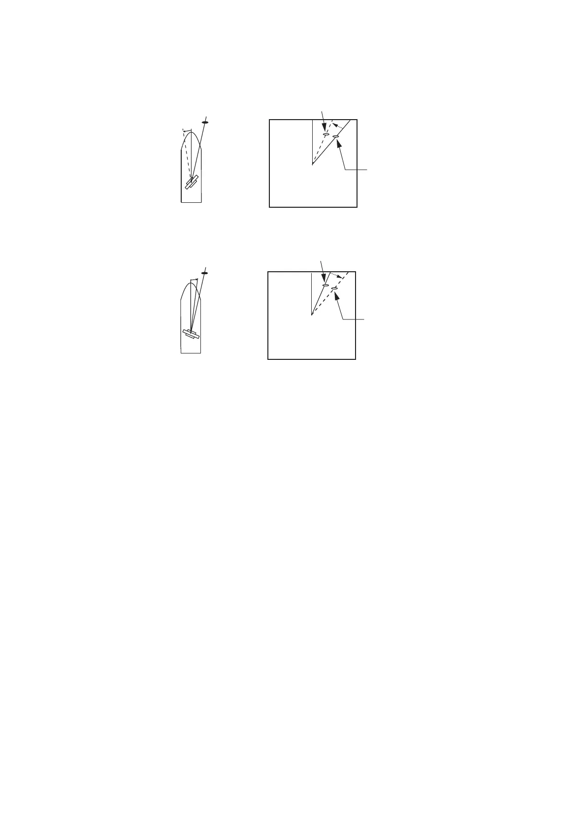
a
Target
a
Correct bearing
(relative to heading)
Antenna mounted error
to port (HDG SW advanced)
Picture appears
deviated clockwise.
b
Target
b
Apparent position
of target
Correct bearing
relative to
heading
Apparent
position of
target
Antenna mounted error
to port (HDG SW delayed)
Picture appears
deviated counterclockwise.
 Loading...