AA-50
C1-2
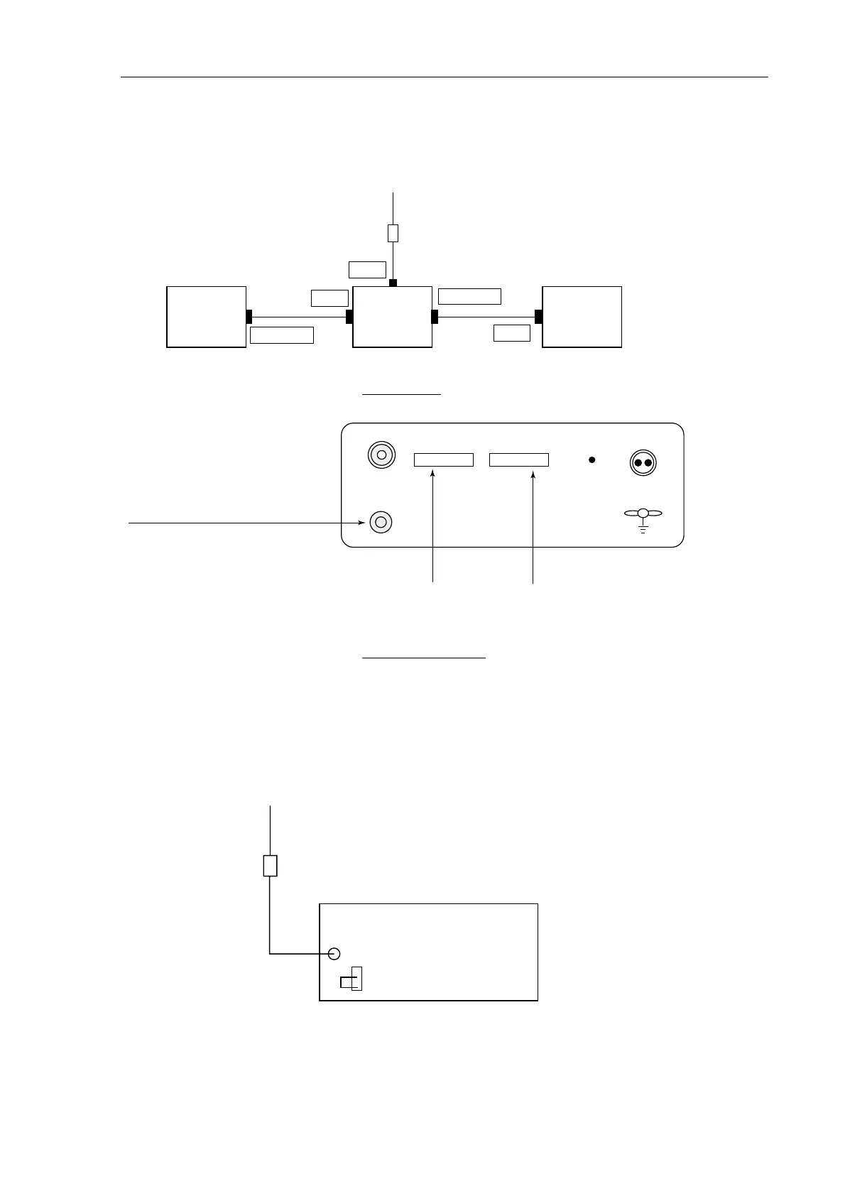
2. Connection
Connection
AA-50 Rear Panel
3. Jumper setting
When the Pre-AMP unit (FAX-5) is installed, the jumper block of J9 on the Receiver
Board must be set to “ACTIVE” to supply about 9Vdc to the Pre-AMP unit.
Note) ACTIVE Antenna : 2.6m Whip antenna + FAX-5
Active
J1
To Antenna
2.6m Whip antenna
FAX-5
Factory setting:Active
Receiver Board
MF-HF T/R DSC
BREAKER
LINE LEVEL
ANT
10.0V-40.0V
0dBm
To DSC Terminal:DSC-5/6To Receiver or Radiotelephon
:RV-xxxG/FS-xxxx
Grounding Terminal
2A
The potentionmeter for adjustment of
LINE OUTPUT LEVEL (+10dBm adjustable)
is on the rear panel.
It is pre-adjusted at the factory (0dBm output)
for use with the DSC-5/6.
DSC-5
or
DSC-6
AA-50 FS-xxxx
DSC
MF-HF T/R
ANT
MF/HF Rx
REM
2.6m Whip antenna
FAX-5
RS-232C RS-232C
J9
 Loading...