REMOTE
I1-13
3.4 Connection
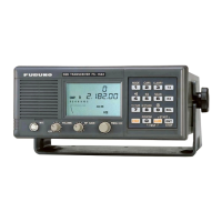
1. Connection to FS-5000/8000
The different modification is required depending on the suffix number of AF board.
For suffix No.-22 and before
The FS-5000/8000 radiotelephone outputs +18V for the RB-500 which operates on +12V.
Therefore, reduce +18V to +12V by adding a resistor as shown below.
Note that this modification is not required if the RB-500 is connected to the
FS-5000/8000 via the DB-500.
Modification
Remove L4 on the MAIN board (05P0483) and install a resistor at the same place
.
Change system setting 9933 to “0”(MIF) on the FS-5000/8000.
[STO] 9933 [ENT] “0”(MIF) [ENT]
For suffix No.-33 and after
The AF board having suffix No.-33 and after is delivered from August 1993.
Note that when FS-5000/8000 is connected to DB-500 in RS-232C format, this
modification is not required.
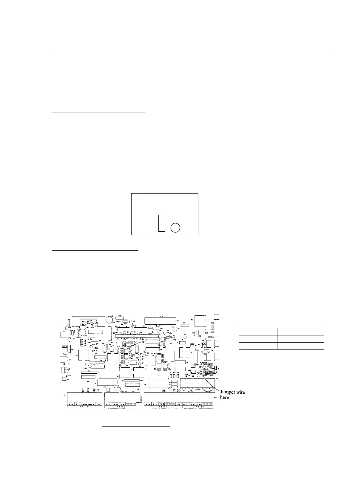
C.Loop or RS-232C format can be selected by changing a jumper wire setting on the AF
board having suffix No. –33 and after.
Br
k
r
MAIN Board
Jumper wire Signal format
short C.Loop
open RS-232C
AF Board (05P0356-33)
 Loading...