FELCOM 82
H3-39
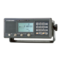
5. Set S6 on the checker to the upper position to commence the call.
CR11 CR12 CR13 CR14 CR15 CR16 CR17 CR18
CR1CR2CR3CR4CR5CR6CR7CR8CR9 CR10
Received Data Pattern
Sending Data Pattern
ON
OFF
RTS
TxD RI DCD DSR CTS
RxCLK TxCLK
RS422
RS232C
ON
ON
OFF OFF
RTS
DTR
DTR RxD
S1S2S3S4
S6
S5
S7
S8S9S10S11S12S13S14S15
6. Wait for about 10 seconds until on/off pattern of LEDs CR11 to CR18 becomes
steady.
7. Change the sending data pattern switch setting, S8 to S15.
CR11 CR12 CR13 CR14 CR15 CR16 CR17 CR18
CR1CR2CR3CR4CR5CR6CR7CR8CR9 CR10
Received Data Pattern
Sending Data Pattern
ON
OFF
RTS
TxD RI DCD DSR CTS
RxCLK TxCLK
RS422
RS232C
ON
ON
OFF OFF
RTS
DTR
DTR RxD
S1
S8S9S10S11S12S13S14S15
S2S3S4
S6
S5
S7
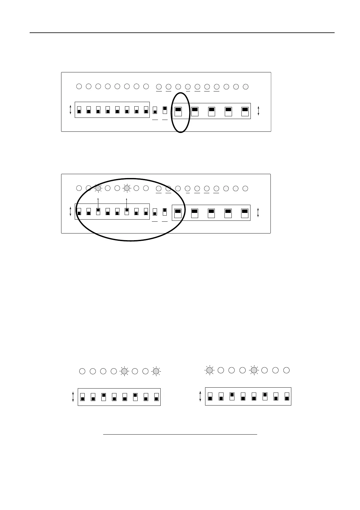
If the on/off pattern of the LEDs CR11 to CR18 changes according to the
sending data pattern switch setting, the HSD works normal. The sending data
pattern switches S15 to S8 do not correspond to the LEDs CR11 to CR18
respectively. The synchronization of both patterns depends on the timing.
In the example below;
Sending data pattern : ON /ON /OFF /ON /ON /OFF/ON /ON
Receiving data pattern:
Left figure : OFF/OFF/OFF/OFF/ON/OFF/OFF/ON
(normal)
Right figure : ON /OFF/OFF/OFF/ON/OFF/OFF/OFF
(abnormal)
CR11 CR12 CR13 CR14 CR15 CR16 CR17 CR18
Received Data Pattern
Sending Data Pattern
ON
OFF
S8S9S10S11S12S13S14S15
CR11 CR12 CR13 CR14 CR15 CR16 CR17 CR18
Received Data Pattern
Sending Data Pattern
ON
OFF
S8S9S10S11S12S13S14S15
Correct receiving pattern Wrong receiving pattern
Sending data pattern and receiving data pattern
8. Set the DTR switch (S6) to OFF position to terminate the call.
9. Change HSD settings for the HSD terminal onboard a ship.
 Loading...