Replaceable parts
2001989-351A ApexPro™ 6-27
5. Fold the retaining clips inward, seating the module into the connector.
NOTE
Do not force the module or retaining clips. If it does not seat easily, the
module may be upside down.
6. Replace the front cover.
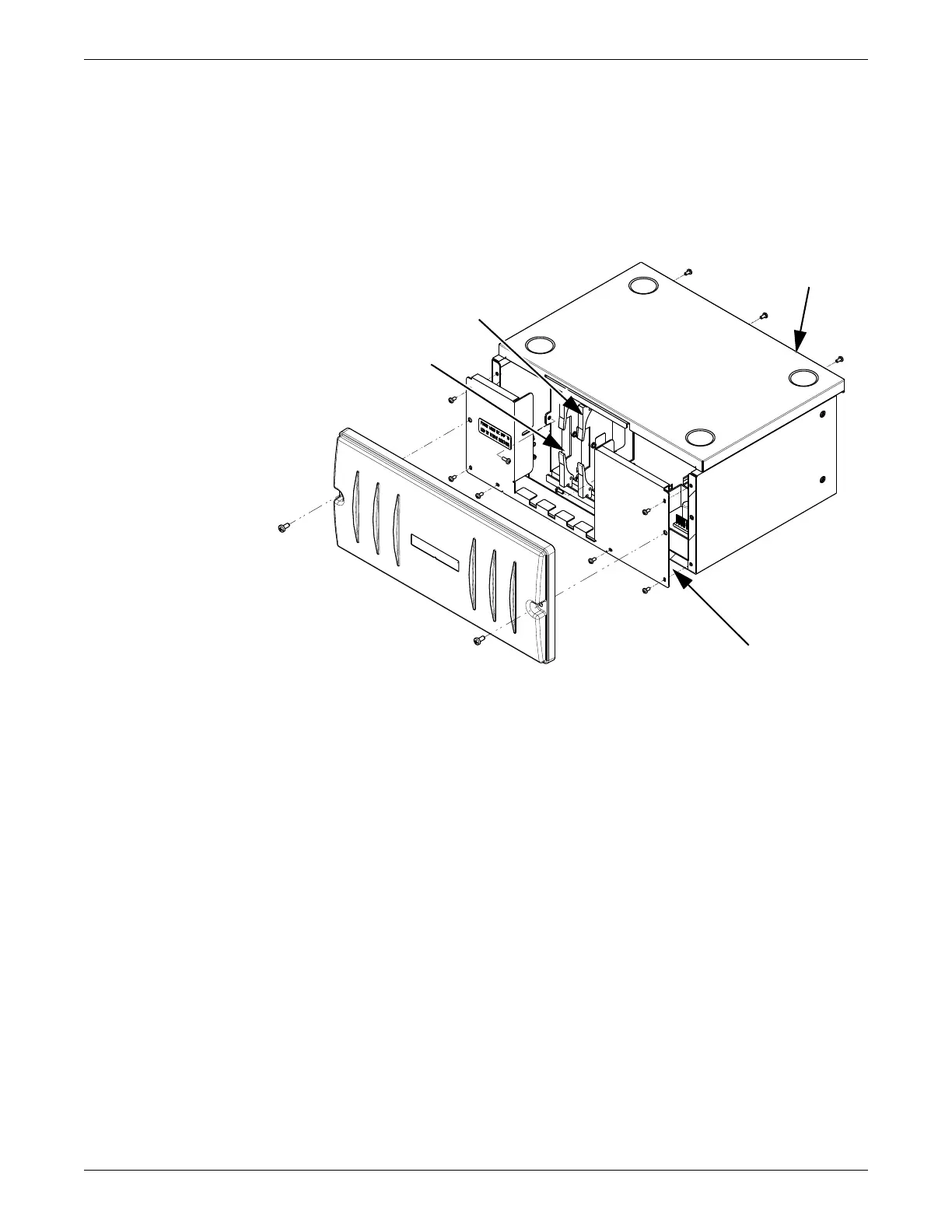
disassy cover
Remove/replace the power supply assembly
1. Remove the front cover as described above.
2. Remove 3 screws from the upper rear of the top cover.
3. Remove top cover.
4. Disconnect the power supply harness from the receiver subsystem pcb.
5. Remove 4 screws holding the power supply to the chassis assembly.
6. Remove power supply.
7. Reverse the above steps to install a power supply assembly.
Remove/replace receiver subsystem pcb (backplane)
1. Remove the front cover as described above.
2. Remove 3 screws from the upper rear of the top cover.
3. Remove top cover.
Top cover
Chassis front
Quad receiver
modules
Retaining clip

 Loading...


