2-14 ApexPro™ 2001989-351A
Equipment Overview
When the battery voltage drops below 1.9 volts for ApexPro,1.6 volts for ApexPro
CH or 1.73 volts for the T14, the Change Battery LED flashes once every second at
a 1/8 duty cycle.
RF
The RF output is transmitted through one of the shield wires on the multi-link cables.
The carrier frequency can be programmed to any frequency within the allowable
band.
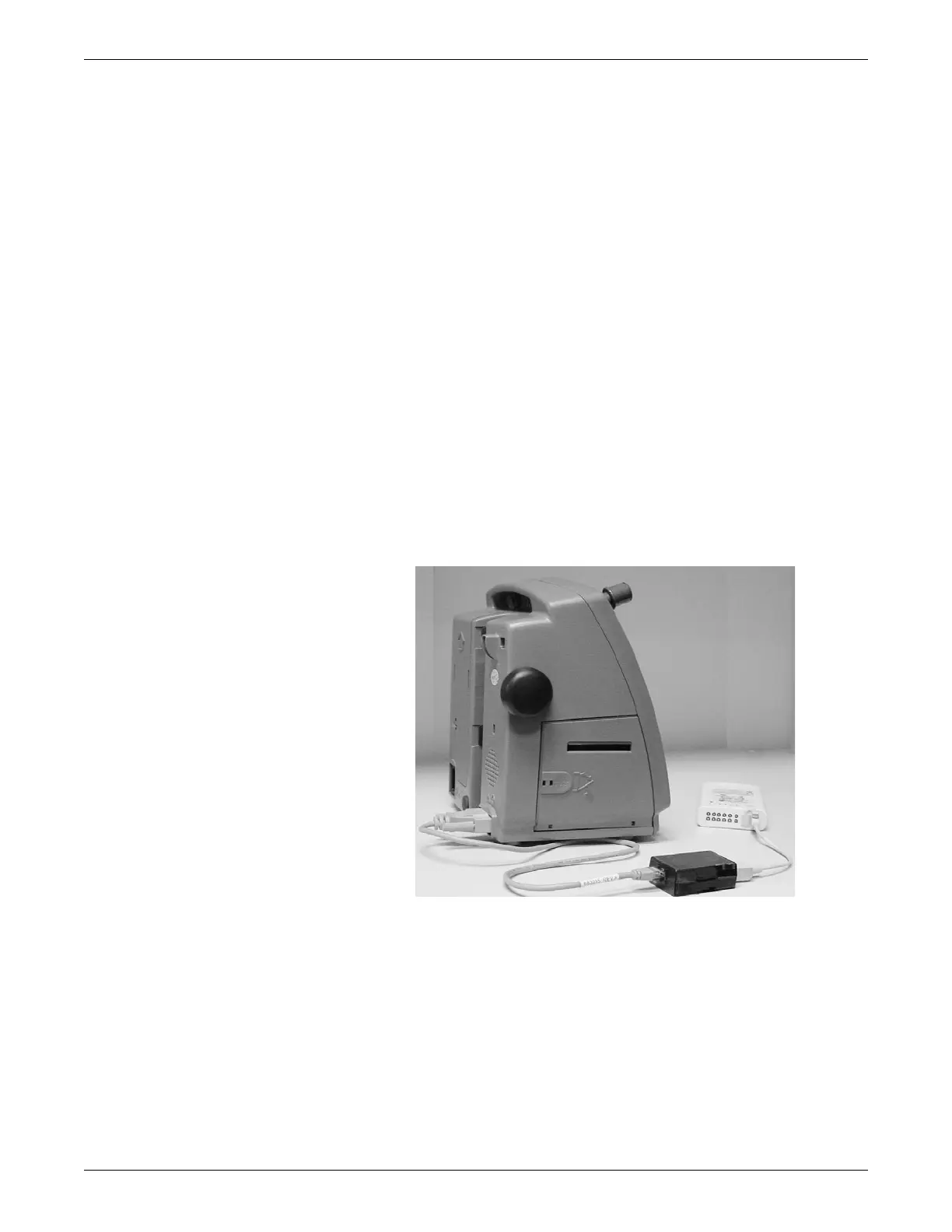
DINAMAP PRO series monitors
The DINAMAP PRO 100, 200, 300, and 400 series monitors can be connected to the
transmitter using the DinaLink™ serial cable to monitor SpO2, NBP, and temperature.
Parameter data from the PRO 100–400 series monitors is displayed, trended, and
stored at the CIC Pro center.
The DinaLink interface cable assembly consists of a monitor adapter cable, the
DinaLink adapter, and an interconnection cable. It connects the transmitter to the
PRO 100–400 series monitors and provides electrical isolation. The interconnect
cable connects to either of the optional interface ports on the transmitter
201A
SpO2 oximeter modules
The oximeter is an optional module that, when connected to the transmitter, allows
telemetry monitoring of a patient’s pulse oximetry data. The oximeter must be
connected to an transmitter in order to convey SpO2 data to the CIC Pro center. Only
digital data is available; no waveforms are generated or transmitted.

 Loading...


