Installation and configuration
2001989-351A ApexPro™ 3-15
If the distance between the ApexPro Telemetry System and the Receiver System
is less than 100 meters (328 ft.) use point-to-point with Ethernet crossover cable
connection.
If the distance is greater than 100 meters (328 ft.) then use either an additional
hub or use fiber optic cable.
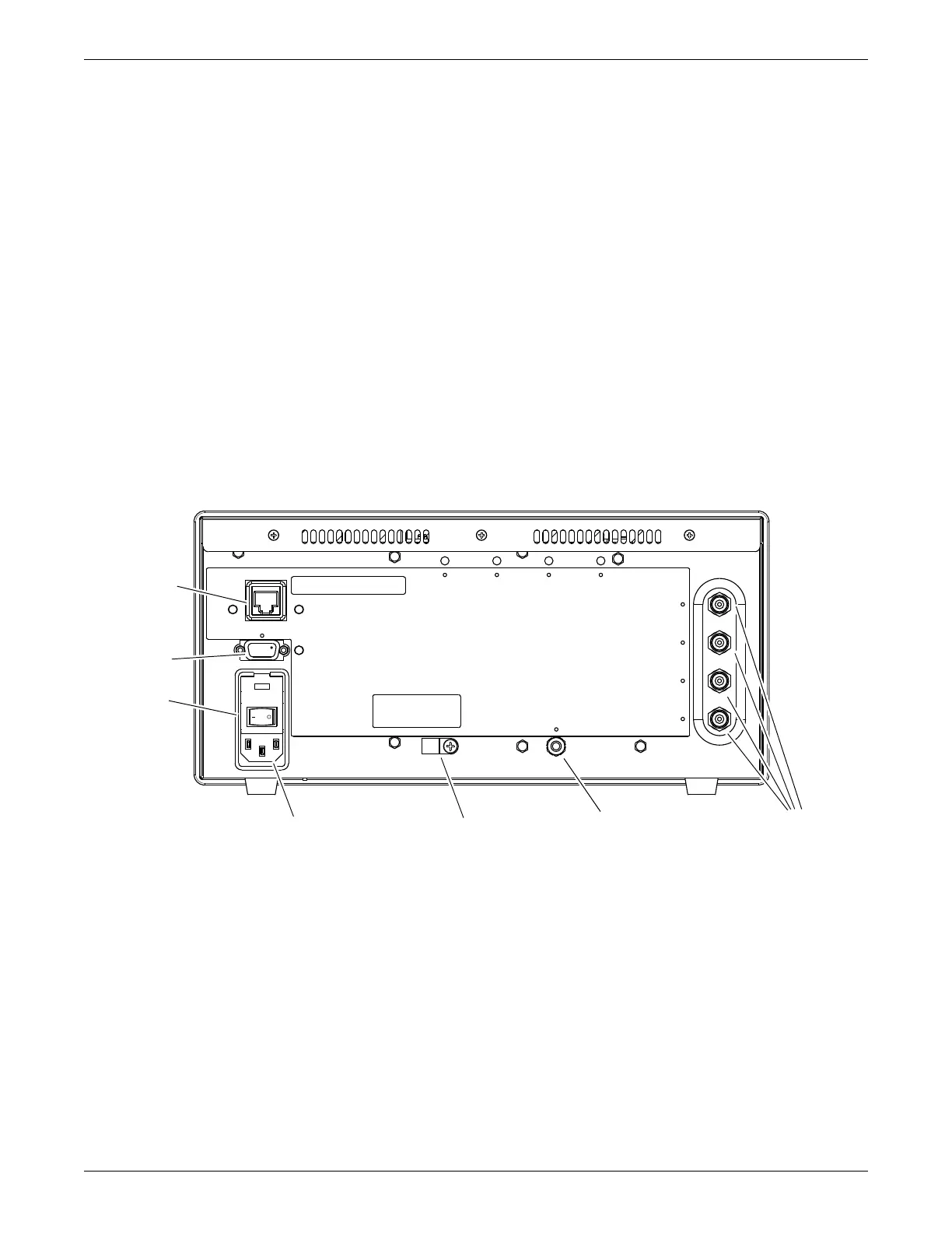
1. Connect the RJ-45 (RX network) to the Ethernet port.
2. Connect the coaxial antenna cables to the antenna inputs. Unused antenna input
jacks need to be terminated with a 75 Ohm F-type male terminator.
3. Connect the power cord to the AC power inlet. Secure the cord with the strain
relief. Plug cord into emergency AC power outlet.
4. Indicate which ApexPro Telemetry System is directly connected by labeling the
Receiver System with the ApexPro Telemetry System name. Place the label near
the RX Ethernet port. If desired, this step may be omitted as the ApexPro
Telemetry System can also be identified by using the Blink Rack command at the
ApexPro Telemetry System.
5. Switch the power switch to I (on).
RearPanel
Setup antenna fields
Use the following procedure for configuring receiver subsystem so that it listens to
antenna fields that are setup.
NOTE
The factory default is that all four fields are enabled.
1. Using the 9-pin, serial cable supplied with the transmitter programming kit,
connect a PC to Async Comm (asynchronous serial communication) for setup.
Antenna
Connectors
Equipotential
Ground
Strain ReliefAC Power Cord
Power
Switch
Ethernet
Async
Comm

 Loading...


