GE HEALTHCARE
DIRECTION 5394141, REVISION 5 LOGIQ™ P5 SEVICE MANUAL
Section 8-2 - DISASSEMBLY/RE-ASSEMBLY 8-9
8-2-3 OSD button and lamp set, LCD Plastic Filter
8-2-3-1 Tools
• Common pilIips screwdrivers
8-2-3-2 Preparations
• Shut down the system and switch off the main breaker.
• Maneuver control console to a suitable position for removing the monitor.
8-2-3-3 Removal procedure
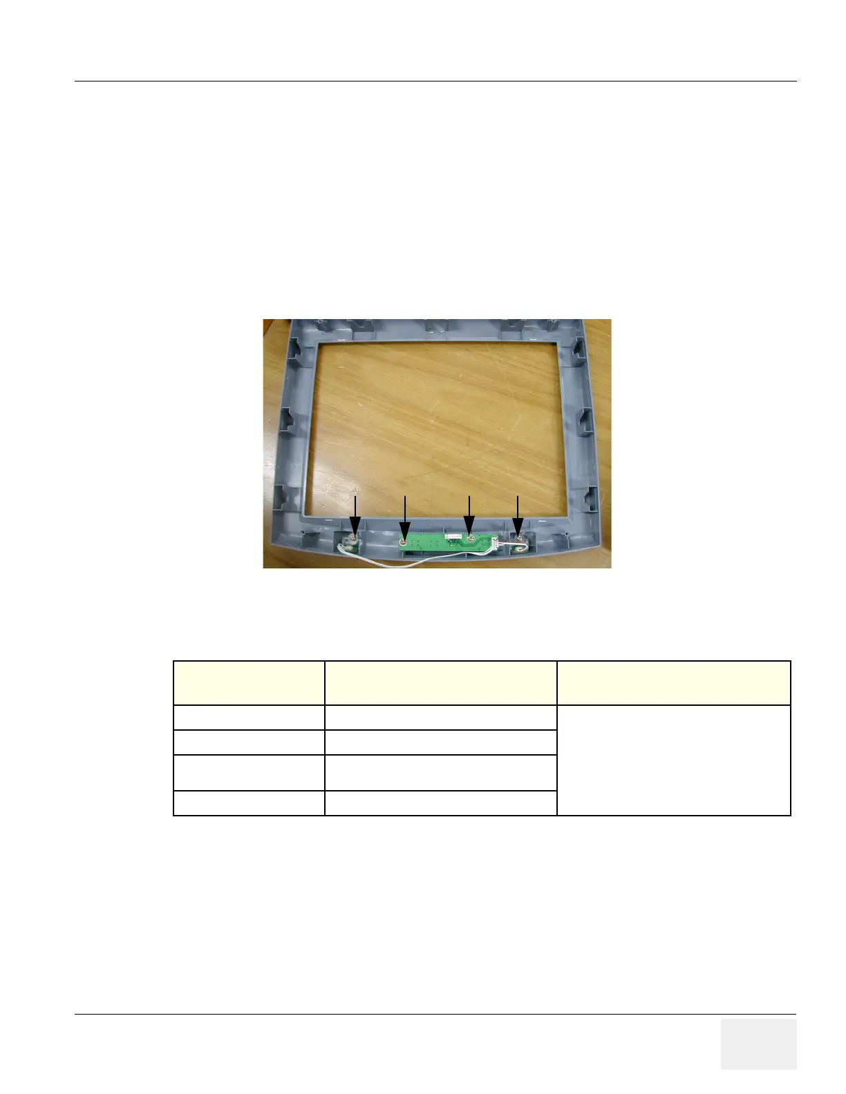
1.) Unscrew 4 screws (1-4) from the LCD front cover.
2.) Perform the following functional tests. If all are successful, include the debrief script provided below.
8-2-3-4 Mounting Procedure
Install the new parts in the reverse order of removal.
Figure 8-12 Unscrews 4 screws
Table 8-4 Functional Tests
Service Manual
Section
Functional Test / Diagnostic Test Debrief Script
Section 4-3-1
Power On/Boot Up
“Service Manual, Direction
5394141, Rev 1+, Section 8-2-3. Equipment
passed all required tests and is ready for use. “
Section 4-3-2
Power Off / Shutdown
Section 4-6-2
15" OSD Key Assy Function Validation
Procedure
Section 10-5-5
Physical Inspection

 Loading...


