ADL300 - Fast installations and commissioning Pag. 11 of 52
4 Electrical Installation
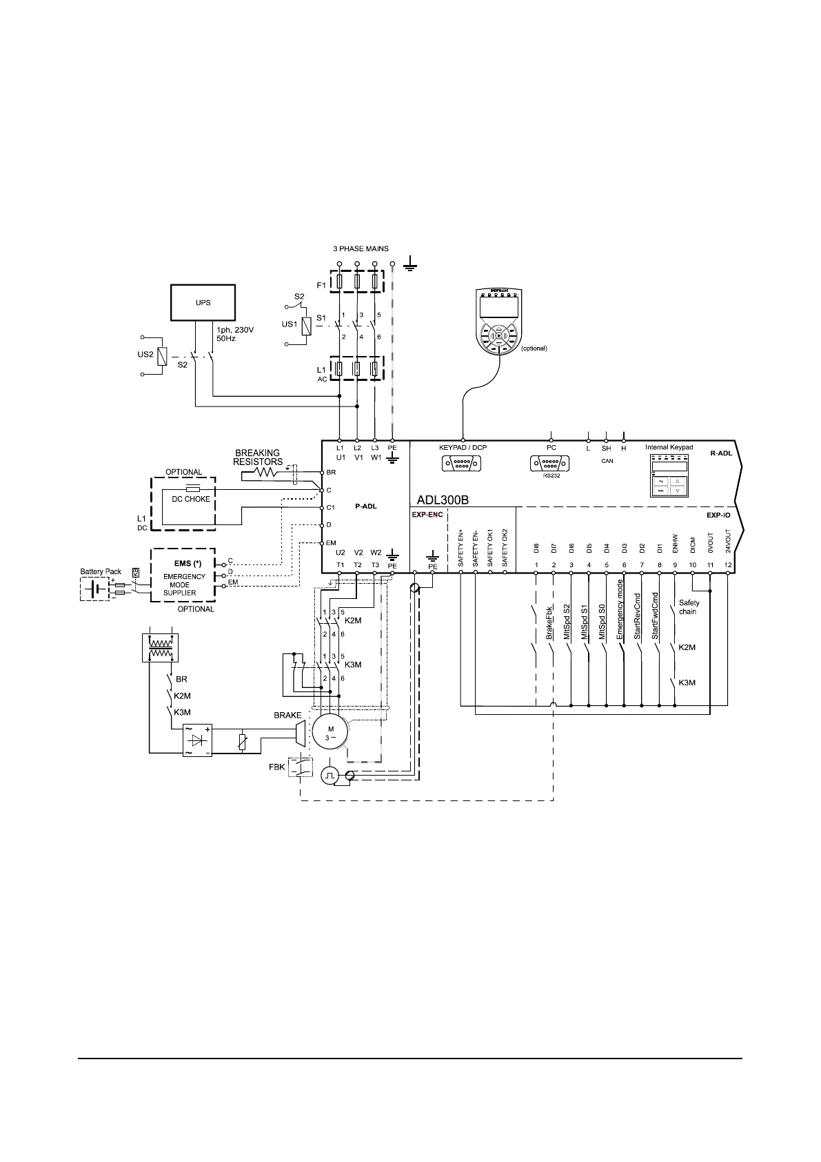
4.1 ADL300 Typical Installation and Main Sections
The ADL300 is composed of two parts where the cables must be connected: power section (P-ADL) and regulation
section (R-ADL). Here a typical connection schema using phase contactors (for single contactor or contactorless
connections see ADL300 Quick Start Manual).
4.1.1 Power Section (P-ADL)
The power section that is supplied by the main and provides the power to the motor. The terminals available in the
power section of the drive are the followings:
• L1 - L2 - L3: terminals for connection to the main
• U – V - W: terminals for connection to the motor
• C – D: terminals for direct connection to the DC bus.
• BR: terminal for the connection of the braking resistor
• EM: terminal for the connection of the Emergency system (see chapter 6.7).
 Loading...