ADL300 - Fast installations and commissioning Pag. 45 of 52
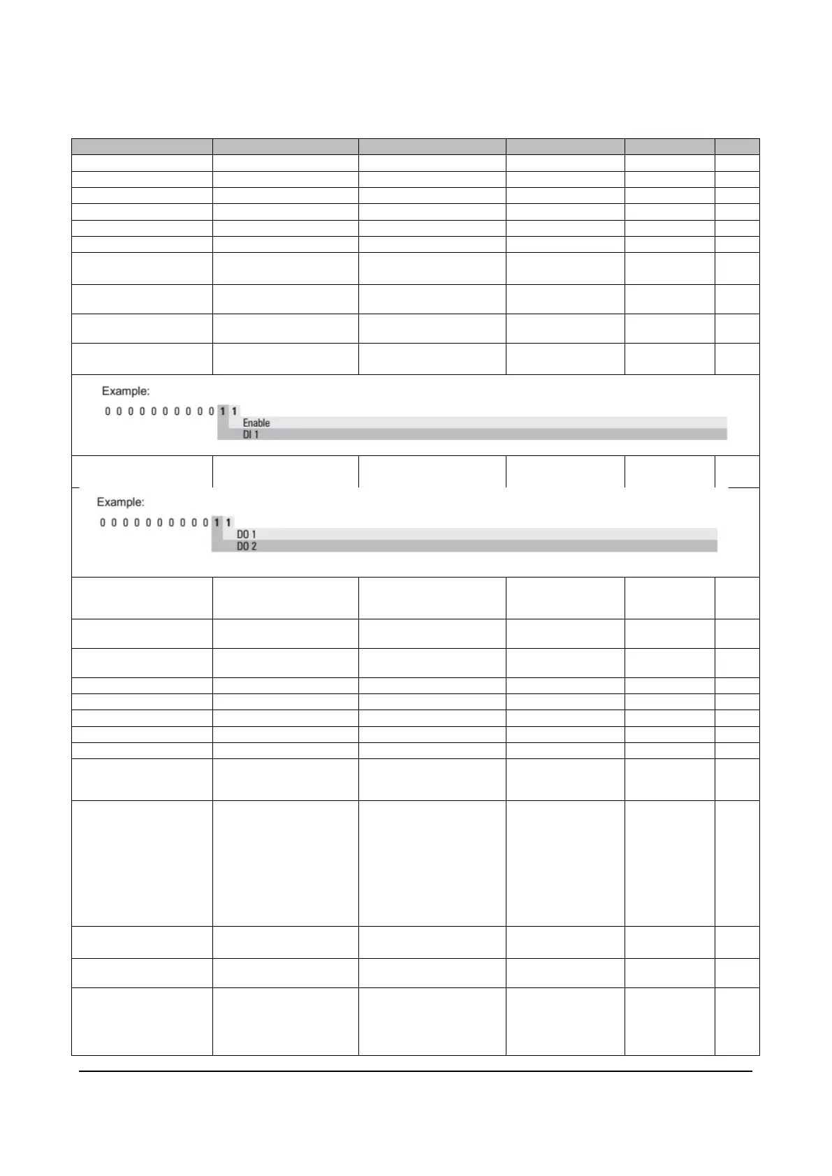
10 Monitoring Parameters
Actual Speed of the motor
Status (Default Dig Input 7)
1 Enabled
Status
The drive Fast Stop Command
Status
The status of the digital inputs
1 Enabled
The status of the digital outputs
1 Enabled
The direct voltage of the
intermediate circuit capacitors is
displayed (DC-Bus)
The temperature measured on
the drive heatsink
The current reference used for
torque control
The actual torque current
The actual magnetizing current
The braking resistor overload
limit is displayed (100% = alarm
threshold)
The drive series identification
code is displayed.
The drives reporting 24V in the
description can be feeded by an
external 24Vdc power supply.
For schematics and connection
diagrams please refer to Quick
Start manual
1 Advanced
2 Basic-VGA
3 Basic-End
128 Basic-Sin 24V
129 Advanced 24V
130 Basic-VGA 24V
131 Basic-End 24V
The control mode is displayed.
12 Synchronous
The drive size identification
code
The available mains voltage is
displayed (e.g. 400V). The
undervoltage alarm refers to
this voltage value.
The condition No poweroccurs
1 230V..480V
2 500V..575V
3 690V
 Loading...