Flying Shear for Roll Forming machines – Instruction manual Pag. 13 / 29
4.2.2 Digital I/O
The drive hardware enable input must be connected to digital input 7.
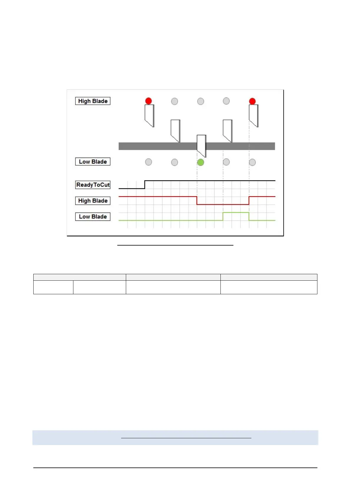
The high and low blade inputs are used to indicate blade position. These are connected to sensors on the
blade as shown in figure 4:
Figure 4: High and low blade sensor operating logic
The output that controls the cut is the output listed in the table::
13 DO3 Cut cmd Pad 2
4.2.3 Encoder
4.2.3.1 Encoder definitions
The encoder mounted on the carriage motor must be defined using the Trolley Enc Sel parameter (PAR
11700, menu TROLLEY).
The metric wheel encoder selection is essential for the system to function properly. The choice depends on
the geometry of the metric wheel and of the carriage.
The encoder resolution used on the metric wheel must be greater than or equal to the encoder resolution of
the carriage motor.
In other words, the ratio between the advancement of the carriage and the carriage motor ppr encoders must
be similar to the ratio between the advancement of the metric wheel and the metric wheel ppr encoders.
The number of the required pprs on the metric wheel encoder can be calculated as follows:
ℎ =
ℎ []
[]
∗
 Loading...


