Flying Shear for Roll Forming machines – Instruction manual Pag. 9 / 29
3 General description
The blade or cutting assembly is fixed onto a carriage that can move forwards and backwards, piloted by the
application. The application measures the length of the material to be cut by a metric wheel binding onto the
material.
For each position of the material from zero up to the cutting length and according to other mechanical
parameters, the application produces the carriage position and therefore the blade position.
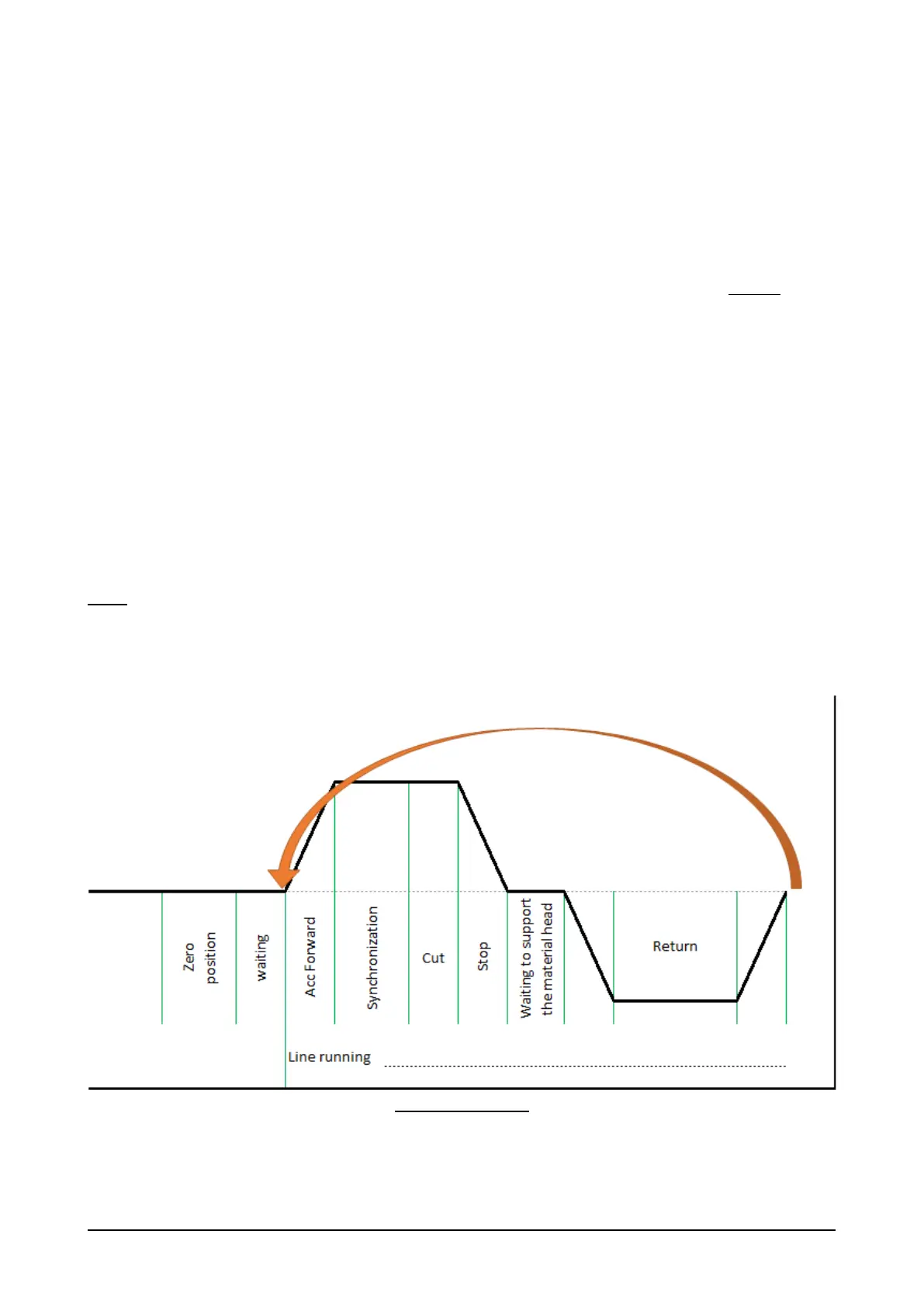
The speed profile is the relationship between the material speed and the carriage speed, see figure 1.
The speed profile consists of:
• At the line’s start up, the trolley moves to the end of the line, supporting the head of the material.
• Once the end of the line has been reached, a standby period can be set, during which the material runs
under the trolley.
• The first phase, when the trolley returns, is for positioning. The position is set based on the line speed,
the cutting time and any safety gaps.
• The second phase is called acceleration forward. During this phase, the trolley reaches the speed of the
material.
• The third phase is synchronization. The carriage proceeds synchronized with the material to reduce
as much as possible any positional error between the carriage and the material.
• The fourth phase is the cut, the application gives the command to let the cut start. The application
proceeds in synchronization with the material up to the end of the cutting space to then resume
immediately with the standby cycle.
Note:
1) Each phase provides for a defined shift using an electric cam, with its position set according to the
different parameters. The space used for each phase is calculated according to the maximum speed
allowed for the material.
2) The space used by the carriage and maximum speed vary depending on the set cutting length.
Figure 1: Speed profile
 Loading...


