Setup
30 312359R
Connect Explosion-Proof
Heaters
Hazardous location sprayers only
(XM_J_ _ and XM_K_ _)
Ensure wiring, wiring connections, switches, and
electrical distribution panel all meet flame-proof
(explosion-proof) installation requirements.
Refer to your Junction Box manual for the wiring
diagram for hazardous locations.
Refer to your Viscon HP heater manual for electrical
connection instructions and guidelines in hazardous
locations.
Refer to your Viscon HF heater manual for electrical
connection instructions and guidelines in hazardous
locations.
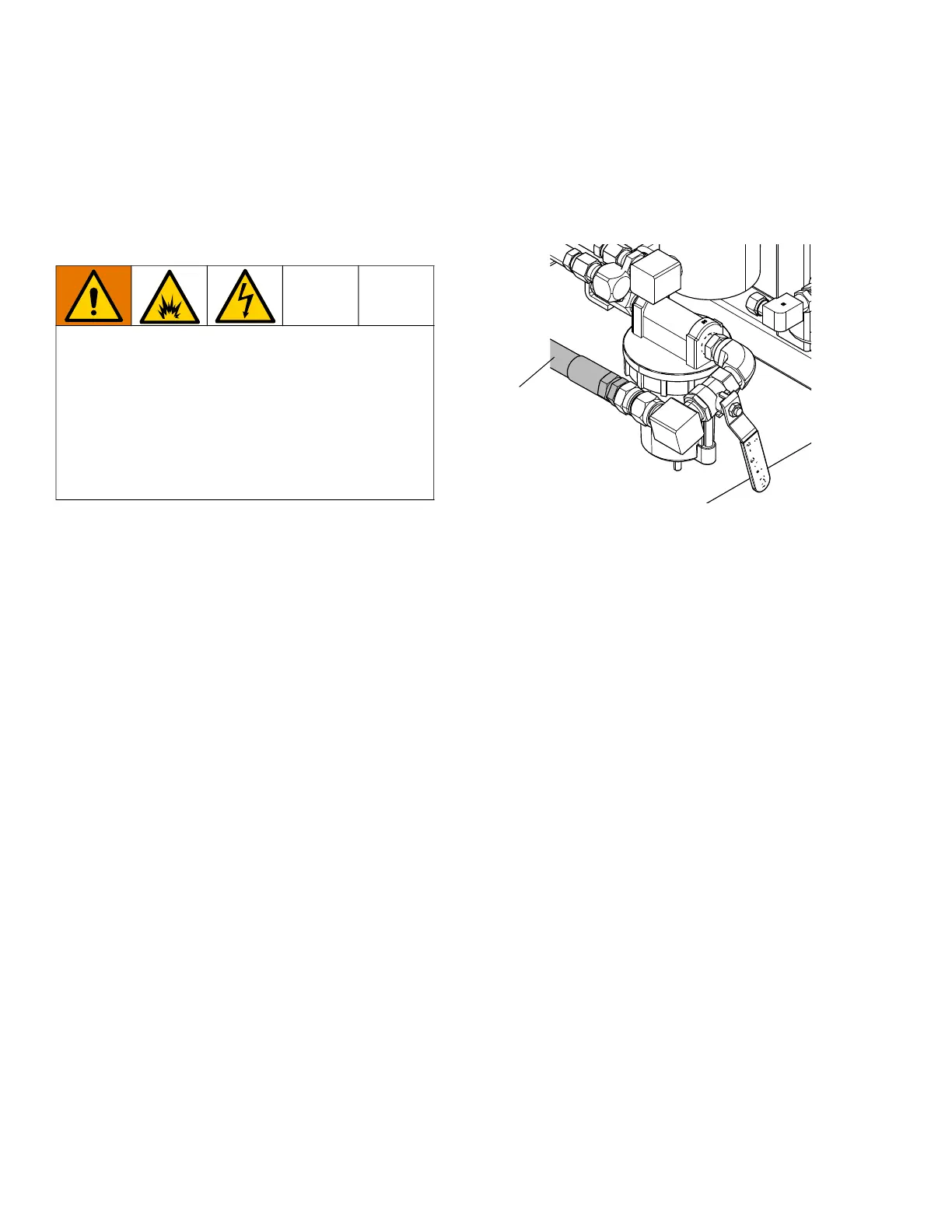
Connect Air Supply
Connect air supply line (SL) to 1.0 in. (10.1 mm) npt(f)
air filter inlet.
Use a 1.0 in. (25.4 mm) ID minimum air hose.
Air supply requirement: 150 psi (1.0 MPa, 10.3 bar)
maximum; 50 psi (0.35 MPa, 3.5 bar) minimum while
running System Verification (page 51), and 80 psi
(0.55 MPa, 5.5 bar) while spraying.
Flow volume required: 70 scfm (1.96 m
3
/min) minimum;
250 scfm (7.0 m
3
/min) maximum. Available fluid
pressure and flow rate are directly related to available
air volume. See Pump Performance Charts, page 102.
General flow volume guidelines:
- 70 scfm (1.96 m
3
/min) per gpm (lpm) while
spraying
- 10 scfm (0.28 m
3
/min) added per agitator
- 10 scfm (0.28 m
3
/min) added per drum feed
pump
If your sprayer is for use in hazardous locations, the
control display (F) is powered by an air-driven alternator.
Dosing valves are operated by air. The dosing valves on
the sprayer will not operate correctly if the inlet air
gauge drops below 80 psi (0.55 MPa, 5.5 bar) while
spraying. The B side dosing valves may not be able to
close, which will result in B overdosing and going off
ratio.
If your sprayer is intended for hazardous locations, a
qualified electrician must connect the explosion-proof
heater wiring. Ensure wiring and installation comply
with local electrical codes and regulations for
hazardous locations.
Improperly installed or connected equipment may
result in fire, explosion, or electric shock. Follow local
codes and regulations.
SL
 Loading...