Appendix C
312359R 95
Appendix C
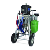
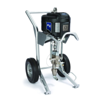
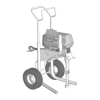
Power Cord Guidelines
Use the guidelines listed in the following table to determine the power cord needed for your specific system.
◆ Wired by user if ordered. Cord size determined by user.
❊ Full load amperes with all components operating at maximum capabilities. Fuse requirements for various flow
rates and heater temperature settings may be less.
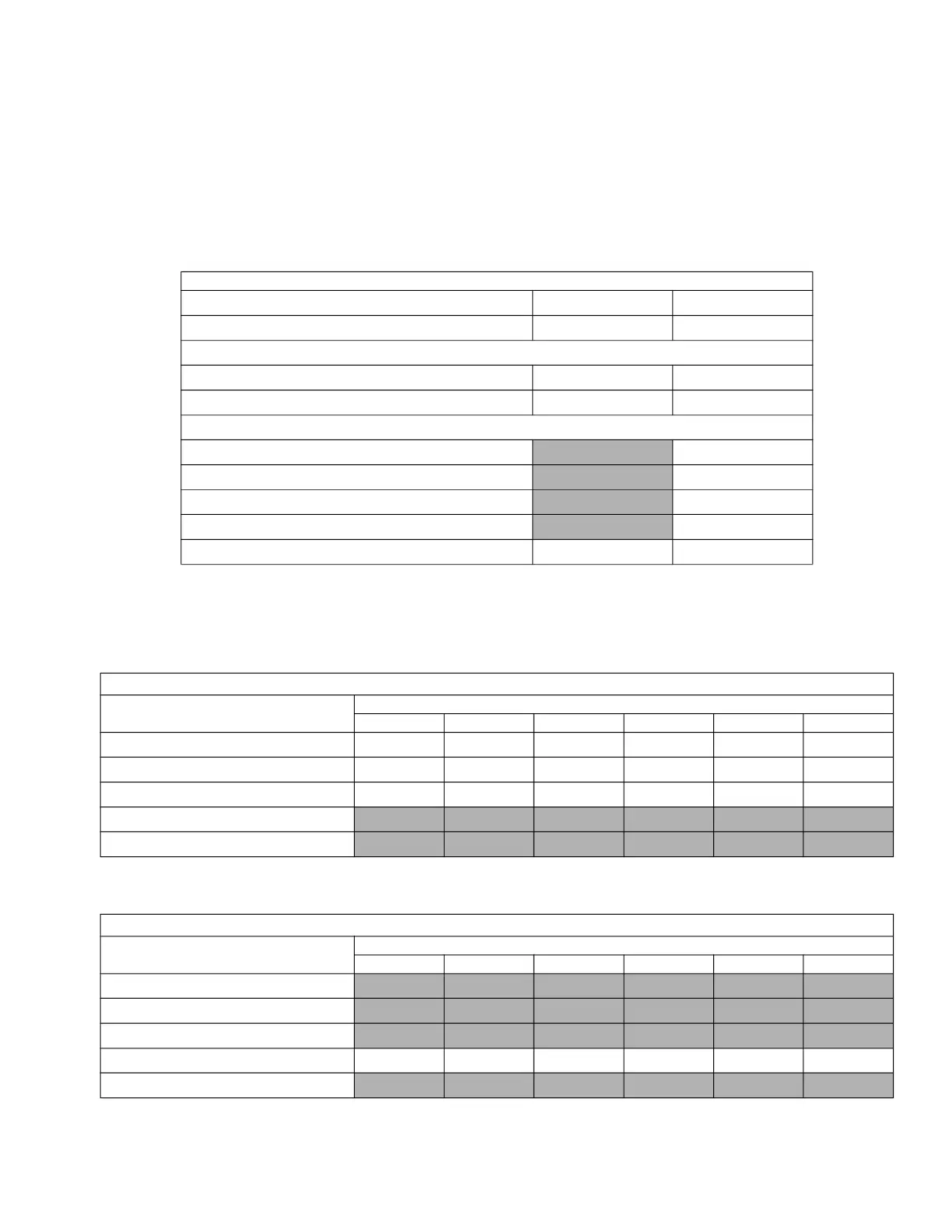
Table 6: Base System Maximum Current Draw
XM_L00 XM_N00
Power Supply Wall Alternator
Configuration Options:
Controls 1 A, 90-240 Vac N/A
❊ Full Load Peak Amperes at 240 V, 1 Phase 1 A 0 A (air only)
Full Load Peak Amperes (A):
240 V, 1 Phase
0
240 V, 3 Phase
0
380 V, 3 Phase
0
480 V
0
100-240 V, 1 Phase
1 0
Table 7: Models with 240 Volt Viscon HF Fluid Heater
Junction Box
Full Load Peak Amperes (A)
XM_ _ 00 XM _ _ 0W XM_ _ 0E XM_ _ 20 XM_ _ 2W XM_ _ 2E
240 V, 1 Phase 46 62 59 71 87 84
240 V, 3 Phase 40 55 52 62 76 73
380 V, 3 Phase 23 40 36 48 48 48
480 V
100-240 V, 1 Phase
◆ Models XM_P, XM_J only
Table 8: Models with 480 Volt Viscon HF Fluid Heater
Junction Box
Full Load Peak Amperes (A)
XM_ _ 00 XM _ _ 0W XM_ _ 0E XM_ _ 20 XM_ _ 2W XM_ _ 2E
240 V, 1 Phase
240 V, 3 Phase
380 V, 3 Phase
480 V 20 20 20 26 28 27
100-240 V, 1 Phase
◆ Models XM_ K, XM_F, only
 Loading...