In-Roof System
Installation
35
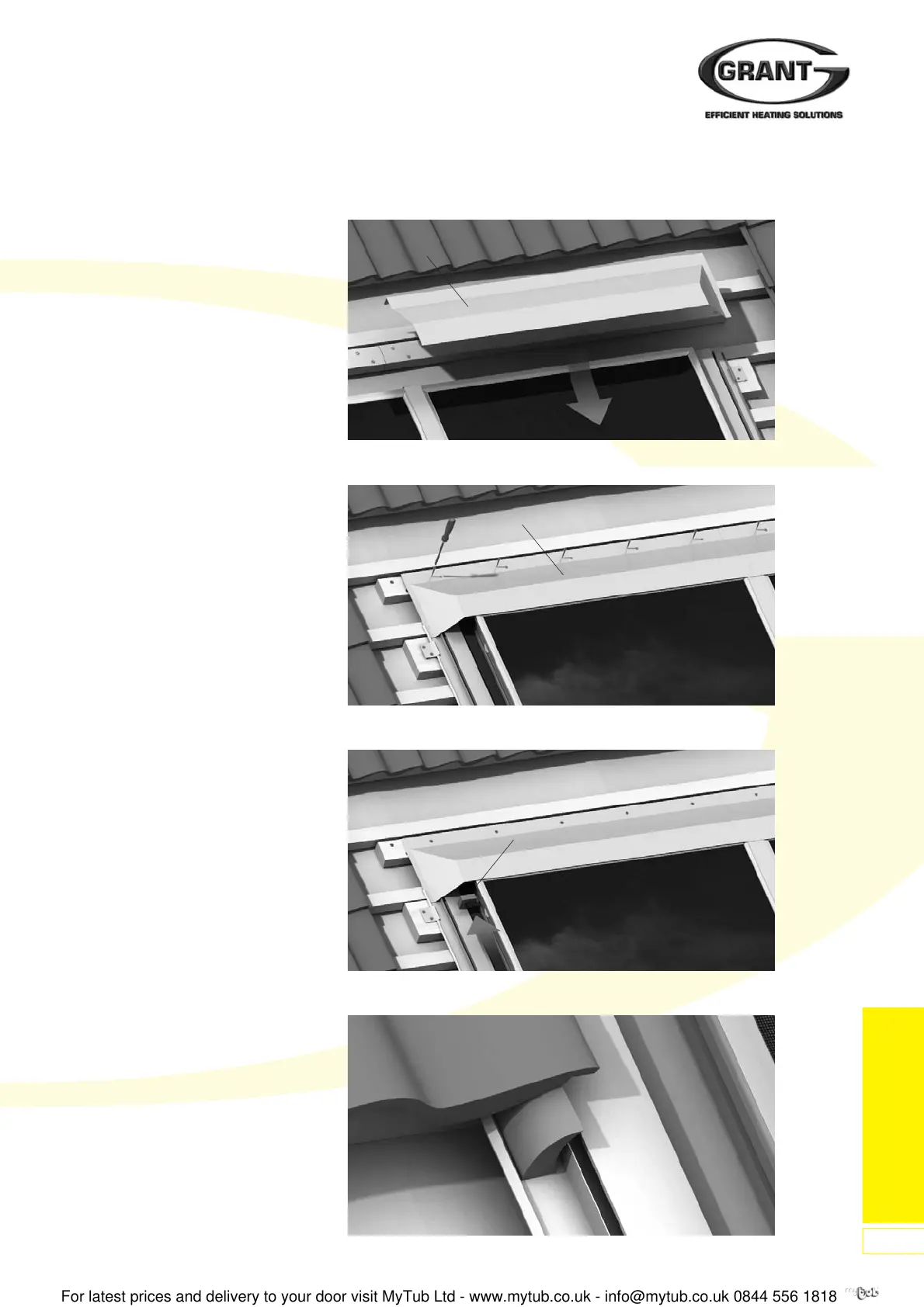
Figure 72: Fitting right Top Cover Flashing (07-B) to Collector
Figure 73: Fixing left hand Top Cover Flashing (07-A)
3. Repeat this process to fit further
closure strips, as required.
4. Fit right hand top flashing first.
Locate slot in lower edge of flashing
onto top edge of collector. Ensure
right hand end of flashing is fitted
INSIDE the return edge on the right
hand side gutter.
5. Fit left hand top flashing onto top
edge of collector, overlapping the
right hand flashing in the centre.
Ensure left hand end is fitted
INSIDE the return on the left hand
side gutter. Fix the right hand
flashing to the batten beneath using
the self-drilling screws provided in
the kit. See Figure 73.
6. At the centre, lift the end of the left
hand top cover flashing and remove
the protective film from the Butyl
tape on the right hand flashing.
Press down the end of the left hand
flashing to seal. Fix the left hand
flashing to the batten beneath using
the self-drilling screws provided in
the kit.
6.6 Closing the Roof
1. If necessary, the right roof tile row
must be cut. It may also be
necessary to remove the upstands
fitted to the roof tiles on the sheet
side (side cover sheet).
Note:
To improve the weather-tightness of
the roof covering, optional foam
wedges can be bonded to the side
flashings before closing the roof
area.
2. Roof tiles above the solar collector
field are usually cut also.
Overlapping for the top cover
sheets must be carried out
according to the following values for
roof incline:
= 35° at least 120mm
> 35° at least 100mm
> 50° at least 80mm
Important:
Following installation the
collectors must be covered, to
stop solar radiation reaching
them, until completion of filling
and commissioning.
Figure 74: Fitting Foam Block (14)
Figure 75: Position of Foam Sealing Wedges
07-B
07-A
14
 Loading...