Differential Controller
Electrical Installation
45
11 Differential Controller
Electrical Installation
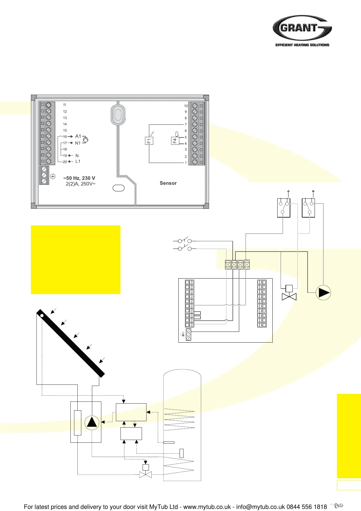
Figure 102: Electrical Connection
Figure 103: Wiring Diagram
11.1 Electrical Connection
Collector
Grant GSD1
Controller
Electrical
Junction Box
Twin-coil Cylinder
Cylinder Thermostat
for bottom coil
Solenoid
Valve
Solar pump
ControlLimit
E
12
c
12
c
3 Amp fused
supply
LNE4
(not supplied)
Pump
Station
Figure 104: System Schematic Diagram
11
12
13
14
15
16
17
18
19
20
10
9
8
7
6
5
4
3
2
1
E
Important - ensure that:
1. the collector sensor (F1) is
correctly located next to the ‘flow’
connection of the collector - refer
to page 36.
2. the storage tank sensor (F4) is
correctly located in bottom sensor
pocket of the hot water storage
cylinder.
 Loading...