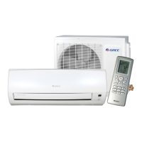
Outdoor unit
1. Confirm that there is no anomalous noise or vibration (other than the nor-
mal known working conditions) during operation.
2. Check the refrigerant circuit: Connect a low pressure gauge with a refrig-
erant hose to the 1/4” SAE service port of the outdoor unit. Confirm that
the female 1/4” hose connection provides a correct adjusted core-
depressor to enable the opening of the “Schrader-valve” inside the service
port.
3. Measure the suction pressure: the suction pressure must be within a
range of 4 to 6 bar (gauge pressure). The system must not be operated
outside the normal running parameters. If it is found that the measured
values differ from these value, it may indicate a malfunction of the system
or indicate a deficit of refrigerant.
4. Search for leakage with an electronic gas detector.
5. After several seconds, close the liquid valve at the outdoor unit in order to
pump the refrigerant to the high-pressure side of the system (pump-down).
This will enable the disconnection of the low-pressure gauge and hose
from the low-pressure valve of the outdoor unit without loss of refrigerant.
Check the pressure of the LP gauge; if the pressure is at 0 bar or slightly
above, remove the gauge with the hose from the LP stop-valve.
6. Open the stop-valve at the liquid side of the system again.
7. Put back again the sealing caps to the valves and the service port.
8. Finally, carry out the search for refrigerant leakage.
After switching off the system, check for the electrical insulation resistance.
Regardless of any other national laws and requirements, the resistance of the
live and neutral wire must be above 7 MOhm.
9. Install the valve cover back to the housing of the outdoor-unit.
Handing over the new system to your client
The client must be comprehensively instructed on the operation and the func-
tions of the system, as well as the handling of the remote control. Show to the
client the relevant pages of the users’ / operators’ manual where they will find
suitable and specific information.
Handover the operation manual to the client, as well as this instruction manual.
Request that the client keeps the technical data sheets and all instruction manu-
als nearby the unit.
For the documentation of the system commissioning and clients instruction, use
the “Start Up Data Sheet” report placed on the following page.
Make sure leak
checking is
done on the
suction side of
the unit without
operation of the
unit. In contrast
check for leaks
to the liquid side
whilst the unit
operates.
Because!
Suction pres-
sure is higher at
the low pressure
site of the
system in “Off”
position!
Pressure at the
liquid stop-valve
is higher under
operational con-
ditions of the
system.
Leaks are better
detected under
higher pressure.
Fill the “Start
Up Data Sheet”
report, sign it
and hand it over
to the client!

 Loading...

