HC Refrigerant Venting—Course of activities sequences 1
Section – Refrigerant Venting
Steps recommended for part 1
No
Where Activities
1
Carry out all intended works without hurry and
THINK BEFORE ACTING!
2
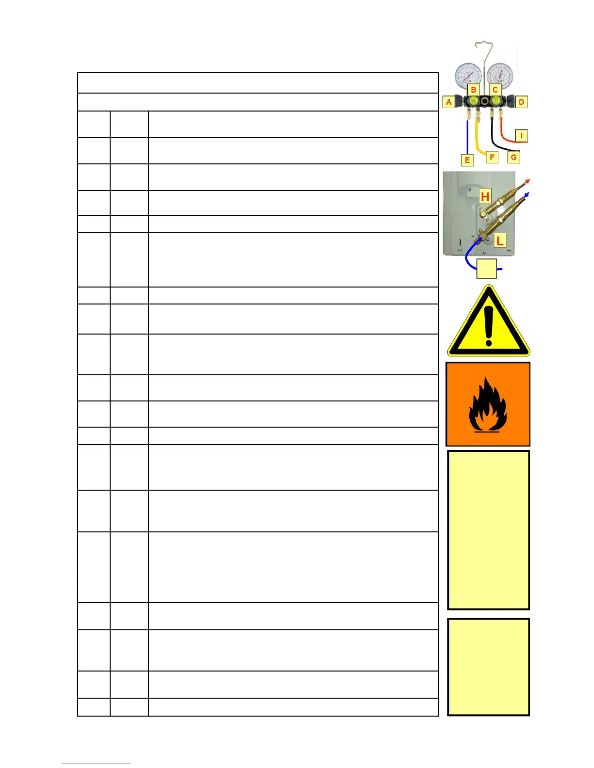
Arrange your tools, manifold and equipment connections as in-
dicated on page 77
4
AC system “OFF“ (unplugged)
5
Place a warning signboard in front of your work area and at the
end of the vent-line to indicate that flammable refrigerant gas
will be vented to the environment and that no unauthorised peo-
ple may enter the safety work area.
6
Smoking and open flames are prohibited.
7
No other sources of ignition must exist within this area
(including your cell phone).
8
Place your HC leak detector on the floor close to your tools ar-
rangement. Switch on the leak detector. If HC refrigerant is de-
tected you will hear the warning signal.
9
Inform other individuals about the safety measures and your
projected time span to maintain all service activities.
10
Assure that all other necessary service tools and spares for the
intended job are in place.
11
Confirm that the circumstances for the intended job are safe.
12
Provide a hose with a length of a minimum of 5 metres (actual
needed length will be according to installation site condition)
and an inner diameter of a minimum of 12 mm.
13
E, L
Assure that the refrigerant transfer hose with the connection at
the suction line service port “L” consists of a core depressor to
open the service port inner core valve during connection.
14
K, G Interconnect the EMPTY recovery cylinder with manifold and
vent-line. The refrigerant hose G must have access to the liquid
port of the cylinder (dip-tube) and the vent-line K to the gas port
of the cylinder. This connection enables oil to be separated in
the cylinder during refrigerant venting process.
15
L
Open the suction side stop valve at the outdoor unit and both
valves of the recovery cylinder.
17
This process should be carried out until no flow of refrigerant is
determined. Pressure at A, C is Zero.
3
A, B,
C, D,
Manifold gauge valves “closed”
16
A, C
Open valves at manifold gauge set. Refrigerant starts venting
and the flow of refrigerant can be easily and safely controlled by
operation of valve A.
18
A
Close the low side valve A at the manifold gauge set.
Consider that
the service port
of the suction
side stop valve
is equipped with
a Schrader
valve.
Hose connection
must have an
adjusted core-
depressor to
open the
Schrader valve
core correctly!
For safe venting
of HC refrigerant
and
Oil-Separation
an EMPTY re-
covery cylinder
is needed!
E
 Loading...