Refrigerant Venting—Part 1
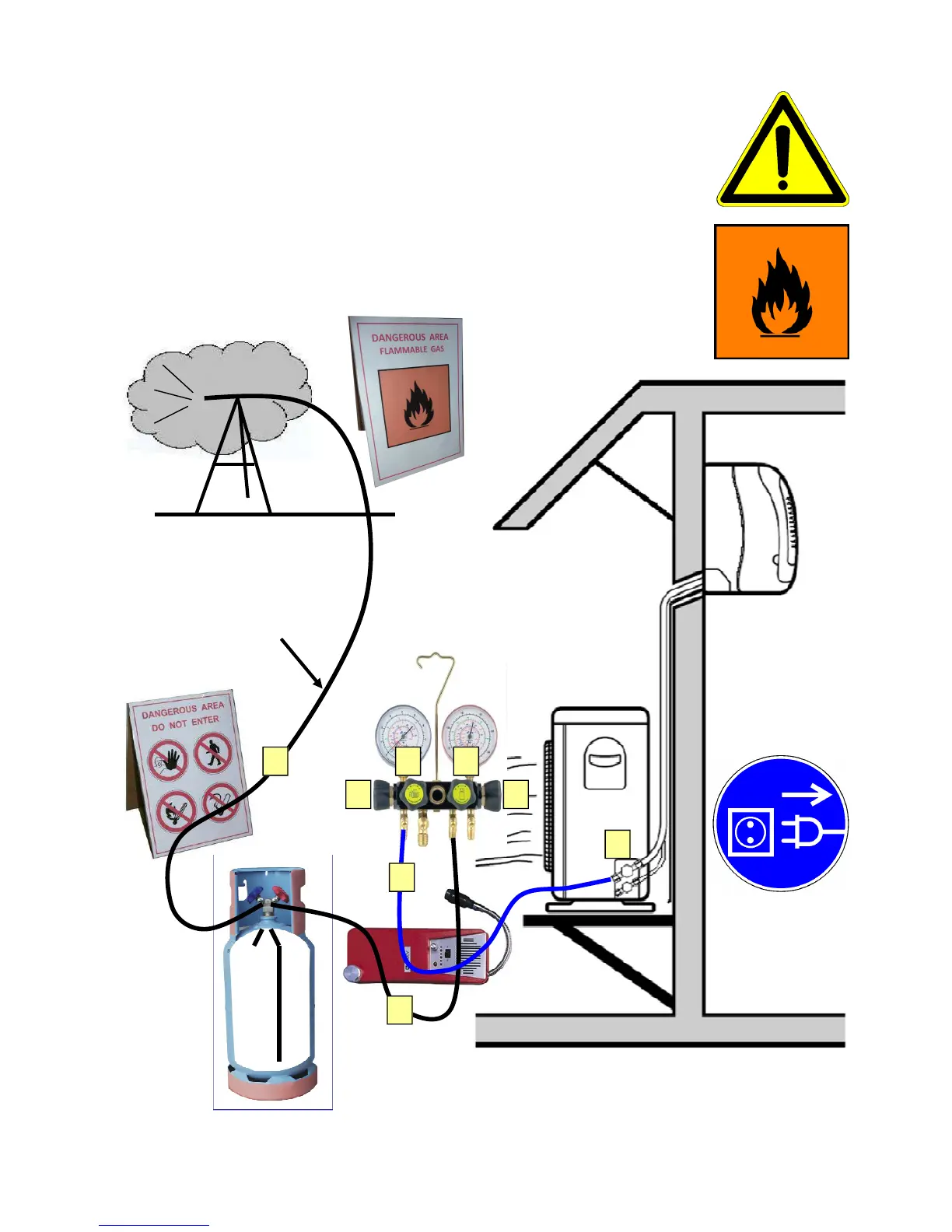
Connect the manifold gauge as indicated below to the service port of the out-
door unit. LP valve port “A” enables to vent the HC refrigerant at a low flow rate
in an easy-to-control manner. The venting of the HC refrigerant takes place via
a two-valve access port equipped recovery cylinder, which will act in this spe-
cific case as an oil separator. The vent-line is connected at the gas valve of the
recovery cylinder. The release of refrigerant transfers lubricant from the outdoor
unit will now remain in the recovery cylinder. The end of the 5 m vent-line is
placed on about 1 m high stand to ensure better dilution of HC refrigerant in air
during the venting process.
A flammable gas warning sign must be positioned close to the hose discharge
port to indicate that there is an occurrence of flammable gas during venting ac-
tivity.
Recovery Cylinder with 2-Valve access
D
C B
A
K
Vent Line
Stand
G
E
L
 Loading...