Section - Refrigerant Circuit Evacuation
Steps recommended
No
Where Activities
1
Carry out all intended works without hurry and
THINK BEFORE ACTING!
2
AC system “OFF” (unplugged) and emptied from HC
refrigerant, OFDN or forming-gas. If necessary purge any left
overpressure from the system.
3
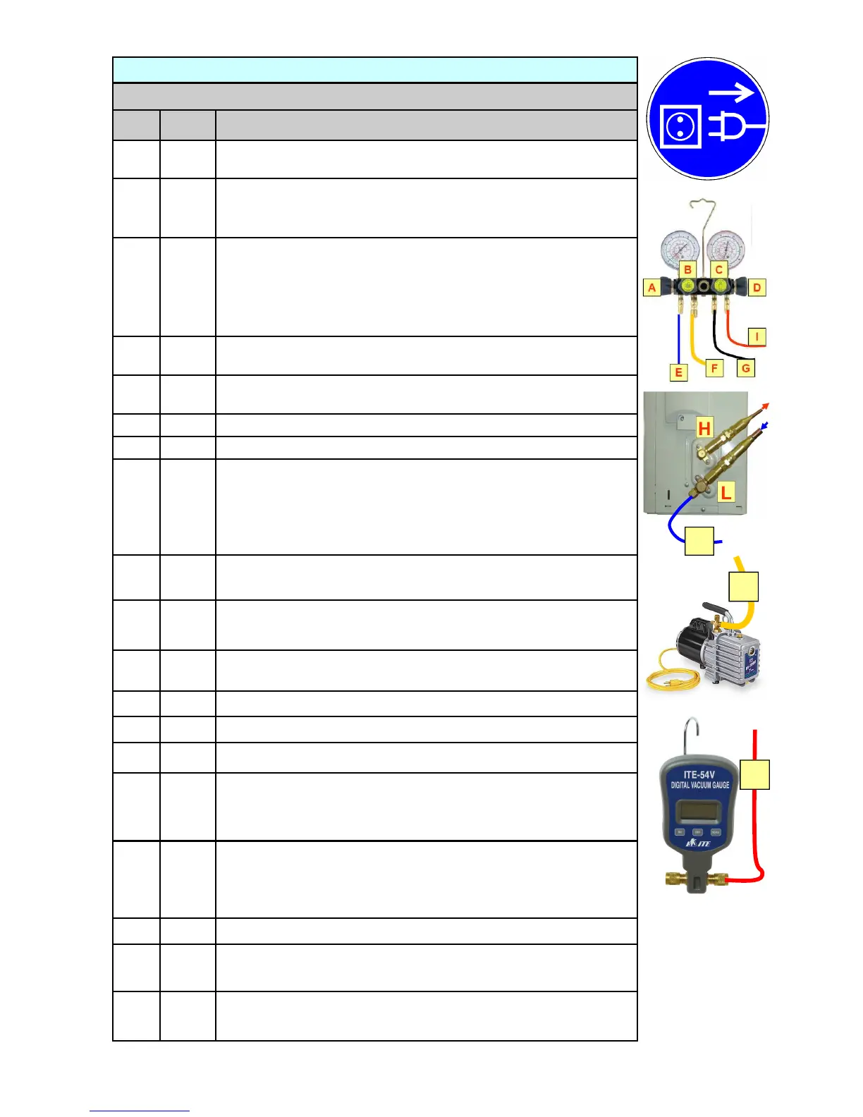
Arrange your tools and equipment connections as indicated on page
96. Ensure that the refrigerant hose “E” with the connection at the
suction line service port “L” consists of a core depressor to open the
service port inner core valve during connection.
The warning sign is
still placed in the work-area.
4
A, B,
C, D
Manifold gauge valves are closed.
5
L & H
Open the stop valves at the condensing units high– and
low- side.
6
A
Open the manifold low-pressure valve.
7
Operate the vacuum pump by plugging in the power plug.
8
Note that placing the vacuum pump at work site should be in
“ON” mode but not connected to the electrical socket! The elec-
trical socket is outside the 2 m safety area. This will avoid
sparking within the safety area with the operation of the “ON –
OFF” switch.
10
B, C,
D
Open manifold gauge valves (vacuum pump, refrigerant cylin-
der, vacuum gauge).
12
Obtain a vacuum of 375 Micron (0.5 mbar or 50 Pa) as
indicated by the vacuum gauge.
13
B
Closed manifold gauge valve (vacuum pump).
14
Switch off vacuum pump remote from plug.
15
Observe vacuum gauge if pressure rises for about 30 minutes.
16
If the pressure rises but does not reach the atmospheric pres-
sure (Zero), it indicates humidity in the system. Open B and
prolong evacuation process.
17
If the pressure rises to 0 bar gauge (1 bar absolute or 100 kPa),
this will indicate that there is a leak in the refrigerant circuit, the
split-unit connections or the manifold gauge and hose assem-
bly. Check system or connections for leaks.
18
The vacuum pressure stays stable.
19
A, C,
D
Closed manifold gauge valves (low-pressure, refrigerant charg-
ing, vacuum gauge).
11
The refrigerant cylinder valve is left closed but the charging
hose “G” will be evacuated during this process.
20
Refrigerant circuit is evacuated and ready for charging with re-
frigerant.
F
I
E
 Loading...