Section - Refrigerant Venting
Steps recommended for part 2 - use of vacuum pump
No
Where Activities
19
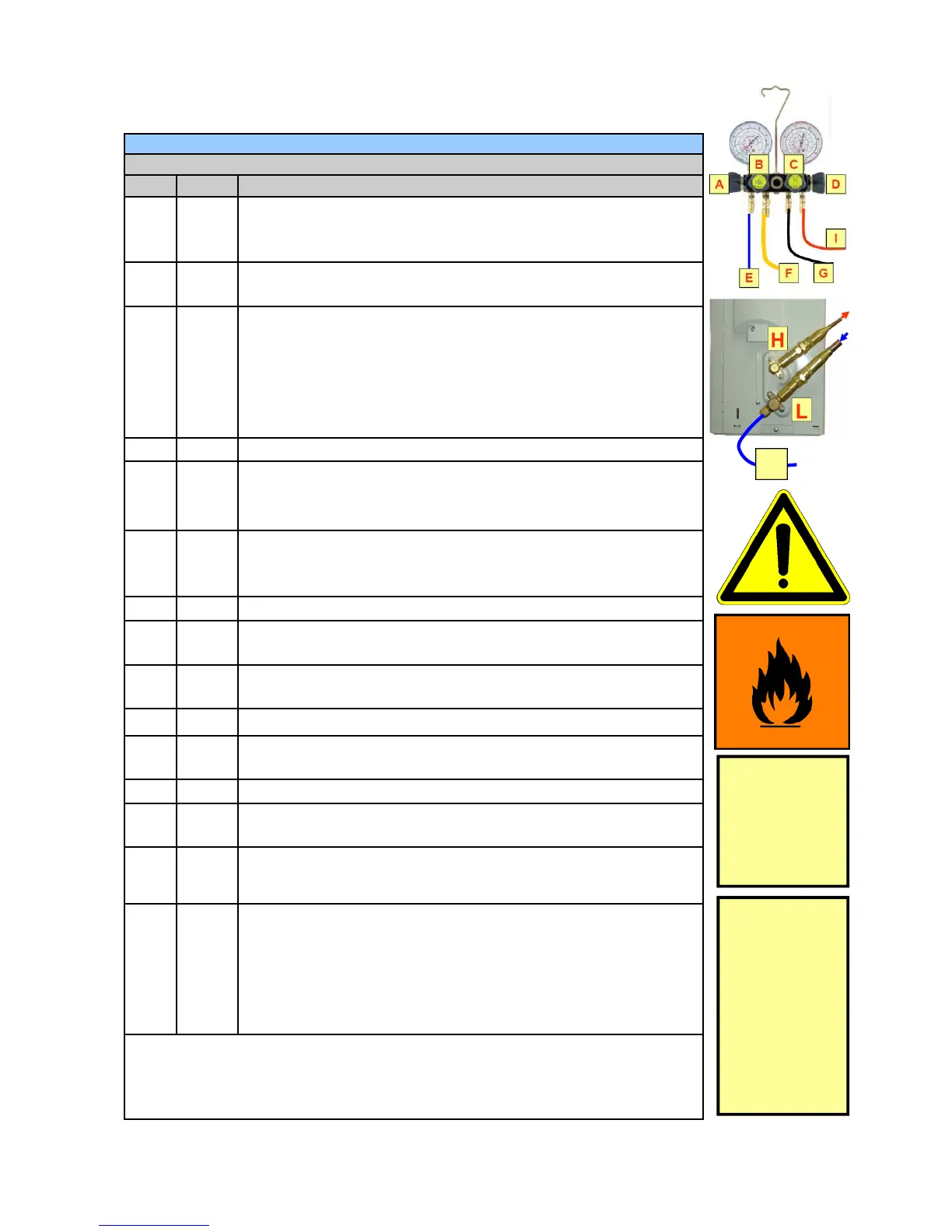
K
Close gas and liquid valve of the recovery cylinder. Disconnect
the vent-line from the gas port of the recovery cylinder (oil-
separator) See sequence 1 from page 78.
20
G, C
Remove the refrigerant hose from the liquid port of the recovery
cylinder. Close valve C.
21
B, F
Place the vacuum pump and connect a ⅜” vacuum hose. The
vacuum pumps On-Off switch is in ON position. Plug and
socket of the vacuum pump are not connected and placed be-
hind the two (2) metre safety area. This will avoid sparking
within the safety area with the operation of the “ON – OFF”
switch.
22
K
Connect the vent-line to the exhaust port of the vacuum pump
23
There should not be a noteworthy overpressure remaining
within the AC system except the out-gassing refrigerant from
the compressors lubricant.
24
Note that higher remaining refrigerant overpressure from
the AC system will damage the vacuum pump during op-
eration!
25
Operate the vacuum pump by plugging in the power plug.
26
A, B
Open the low side valve A and the vacuum pump valve B at the
manifold gauge set.
27
Operate the vacuum pump for about 20 minutes to remove
most of the remaining R-290 refrigerant from the AC system.
28
End of the HC refrigerant recovery and venting process.
29
A,B,C,
D
Valves at manifold gauge closed
30
L, H
Stop valves at the outdoor unit closed
31
Disconnect the vacuum pumps plug connector from power-
socket (outside the 2 m safety area).
32
Remove the venting hose from the vacuum pump. Remove the
manifold gauge set with hoses from the outdoor unit.
33
Place the recovery cylinder at the venting area where the flam-
mable gas warning sign is placed and open the gas valve to
vent any remaining HC gas from the cylinder. Drain the oil from
the cylinder, (gas-valve) by holding the cylinder upside-down, in
an appropriate container for used and contaminated lubricants.
Note:
The recovery cylinder for “oil-separation” should be used regularly for this pur-
pose since the contamination with oil will not classify this cylinder for further
activities with refrigerant, if not cleaned inside professionally.
The vacuum
pump is used to
recover the re-
maining HC
refrigerant
from the AC sys-
tem.
For safety
reasons the
vacuum pump is
switched ON
and OFF by put-
ting in the plug
into the socket.
Plug and socket
are placed be-
hind the two (2)
metre safety
area.
HC Refrigerant Venting—Course of activities sequences 2
E
 Loading...