Section – Trace Gas Leak Detection
Steps recommended
No
Where
Activities
1
Carry out all intended works without hurry and
THINK BEFORE ACTING!
2
AC system “OFF“ (unplugged) and emptied from HC refrigerant.
3
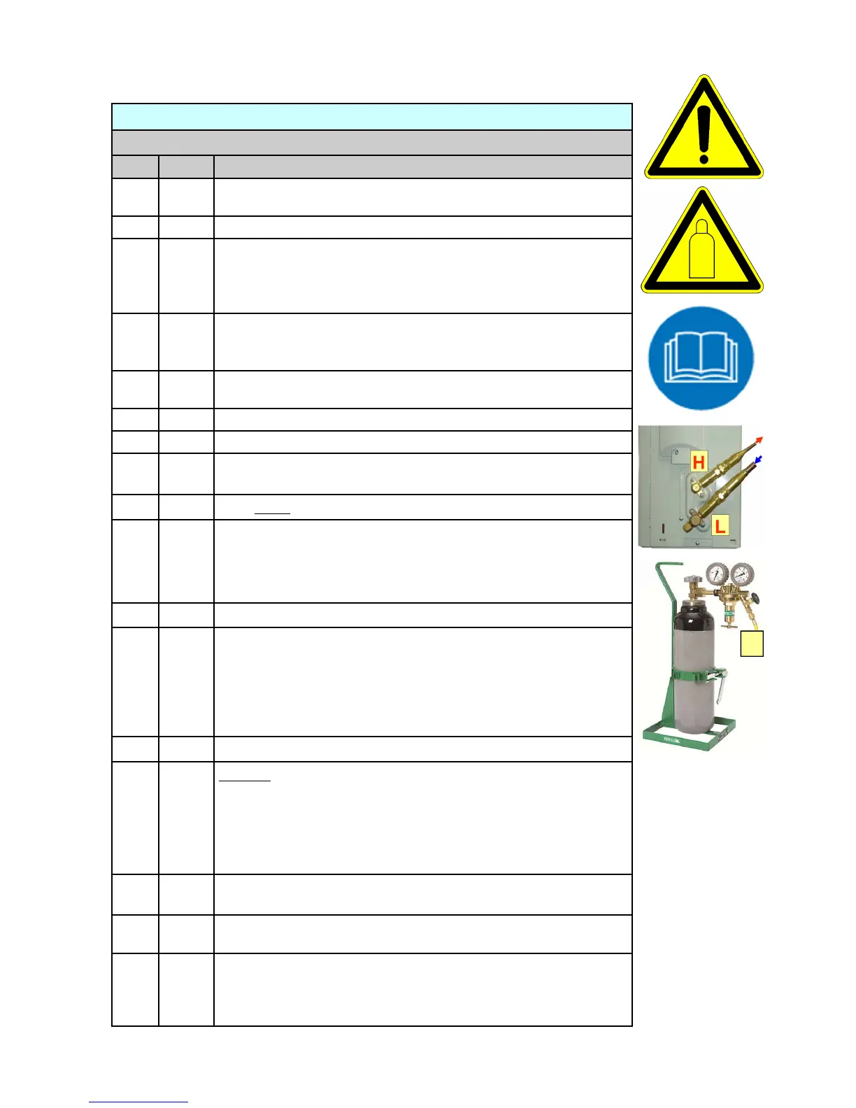
Arrange your tools and equipment connections as indicated on page
92. The pressure adjusting handle (screw) of the pressure regulator
is back-seated. The cylinder valve and the pressure regulators outlet-
valve to the trace gas transfer hose (T) is closed!
4
T, L
Ensure that the trace gas transfer hose with the connection at the suc-
tion line service port “L” consists of a core depressor to open the ser-
vice port inner core valve during connection.
5
T, L
Connect the trace gas cylinder with transfer hose T to the service port
of the outdoor units low-side stop valve L
6
H, L
Open the outdoor units low-side and high-side stop valves.
7
Open the trace gas cylinder valve
8
Adjust the pressure regulators pressure adjusting handle (screw) to
about 5 bar (72.5 PSI) shown at the delivery pressure gauge
9
Open slowly the pressure regulators outlet-valve
10
Trace gas is now transferred into the complete AC system. Continue
the transfer of gas until there is no further flow audible (pressure
equalisation) and 5 bar (72.5 PSI) is indicated. Watch the gauge for
pressure loss!
11
Close the pressure regulators outlet-valve
12
Carry out the Leak Test and hold the sensor head of the trace gas
leak detector as close as possible over the heat exchangers, refriger-
ant transferring pipes and mechanical connections. Move the sensor
head slowly along the components with a maximum of 0.2 cm per
second of speed. Repeat the screening test until you are confident
that no leaks exist.
13
T, L
Remove the trace gas transfer hose from the service port
14
Carefully open the service ports Schrader valve using a valve “pin”
depressor (e.g. small screw-driver) and blow-out trace gas charge. If
necessary hold a piece of old cloth (or paper) into the flow stream to
keep eventually escaping oil from the system. Do not inhale the es-
caping gas. Leave a slight overpressure in the system. Ensure venti-
lation of the work space during gas venting.
15
If a leak was found in step 12, repair the leak or replace the leaky
component and continue with step 5 and 7 to 14.
16
H, L
Close the outdoor units low-side and high-side stop valves (front-
seated position)
17
Close the trace gas cylinder valve. Return the pressure regulators
adjusting handle (screw) in its back-seated position. Purge the pres-
sure regulator from the outlet-valve (pressure regulator is now dis-
charged).
N
2
/H
2
Trace Gas Leak Detection — Course of activities sequences
T
N
2
/H
2
 Loading...