16 HARDI
®
COMMANDER OPERATOR’S MANUAL
Direct Acting Hydraulic system (D.H.)
(optional)
Installation of control box
1. Connect the plug A to the tractor’s 12V power
system. Try to hook up the handle as close as
possible to the battery power supply. HARDI
®
recommends using an electric distribution box (ref.
no. 817925) to ensure a good power supply to
various 12V attachments.
Note: Check with your dealer or tractor operator’s
manual for the best location to hook up the 12V system.
Note polarity: BROWN wire = Positive (+)
BLUE wire = Negative (-)
2. Route the cable with the 7 pins, from the sprayer’s
hydraulic mount plate to the tractor.
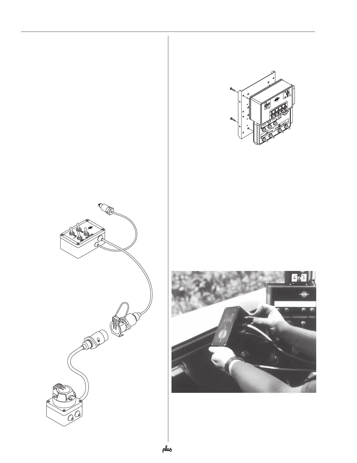
3. Mount the hydraulic control box B in a suitable
location in the tractor cabin.
4. Connect the female 7 pin plug C from the switch box
to the 7 pin male plug D from the sprayer.
Control boxes and power supply
The control boxes for the ECP operating unit are fitted
in the tractor cabin in a convenient place. Self-tapping
screws can be used for mounting.
Power requirement is 12V DC.
Note polarity: BROWN wire = Positive (+)
BLUE wire = Negative (-)
The wires must have a cross sectional area of at least
12wg (4 mm
2
) to ensure sufficient power supply. For
the ECP operating unit the tractor circuit should have
an 8 Amp fuse (5 Amp fuse for hydraulic system).
The 12V power sockets on the control boxes can be
plugged directly into either a HARDI
®
4 outlet connec-
tion box (#817925) or a single female bayonet style
plug (#260827). Both of these are available from your
HARDI
®
Dealer.
Sprayer setup
C
D
B
A
Ø4.8 x 9.5mm
Ø4.8 x 12mm
12-volt junction box (#817925) for 12-volt hook-up.
 Loading...