Harman® • P42i Pellet Insert Installation Manual • 2023 -___ • 08/2317 8742-901D
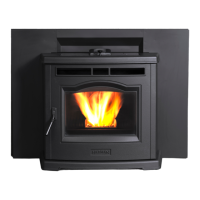
Stub Mounting Bolts
Intake Stub
Stub Gasket
Self-drilling screws (2)
Outside Air Intake Weldment
E. Outside Air
TheoutsideairkitconsistsofaIntakeStub,StubGasket,
OutsideAirintakeWeldmentandhardware.Figure4.7.
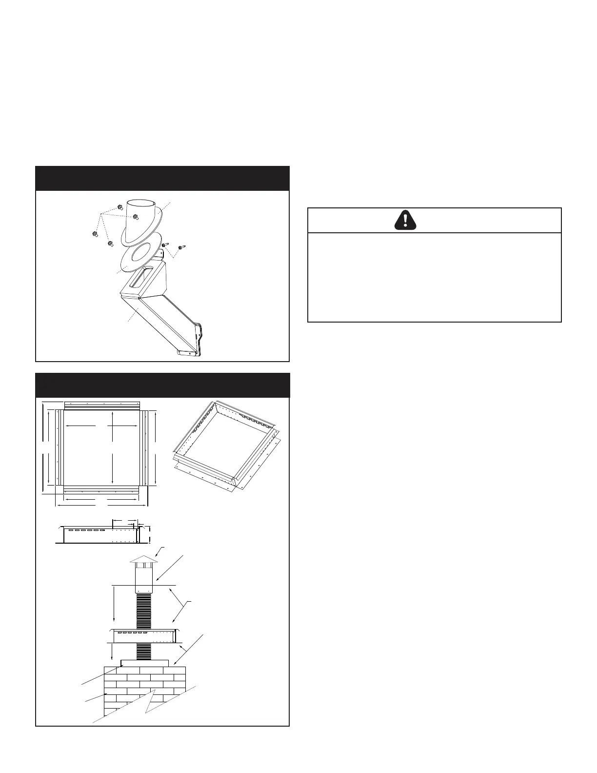
Anadjustablechimneyintakeextension,part#1-00-674104
is available to be used on masonry chimneys only. Figure 4.8.
Additional information and diagrams can be found under the
“Venting TerminationDesign”sectionofthemanual.
Toinstalloutsideair,usekitpart#1-00-574350.Followthe
installation instructions provided with the kit.
100%OutsideAirKit-#1-00-574350
Figure 4.7
F. Locating Your Appliance & Chimney
Locationoftheapplianceandchimneywillaectperformance.
• Installthroughthewarmairspaceenclosedbythebuilding
envelope. This helps to produce more draft, especially
duringlightinganddie-downofthere.
• Penetrate the highest part of the roof. This minimizes the
eectsofwindloading.
• Locate termination cap away from trees, adjacent
structures, uneven roof lines and other obstructions.
• Minimizetheuseofchimneyosets.
• Considertheappliancelocationrelativetooorandceiling
and attic joists.
Chimney cap and flex termination with
flashing plate (by installer) THIS CAP
MUST BE Stainless Steel
With the intake assenbly anchored into
place, finish the 4” SS flex liner and cap
(by installer) by screwing the cap’s flashing
plate to the top of the intake assenbly.
A waterproofing sealant can be used to
seal the corners and irregularities in the top
of the masonry chimney.
After adjusting the intake assembly
for the flue size, secure the
assembly to the top of the chimney
with some form of anchors or
screws.
Masonry Flue Liner
Masonry Chimney
AdjustableChimneyIntakeExtensionPart#1-00-674104
18 1/8”
18 1/8”
18”
18”
22 1/8”
18”
22 1/8”
4”
6”
1”
Harman® SS Chimney Top Intake Assembly
• DONOTCONNECTTHISUNITTOACHIMNEYFLUE
SERVICINGANOTHERAPPLIANCE.
• DONOTCONNECTTOANYAIRDISTRIBUTIONDUCT
ORSYSTEM.
Mayallowuegasestoenterthehouse
CAUTION
Figure 4.8
 Loading...