Harman® • P42i Pellet Insert Installation Manual • 2023 -___ • 08/2325 8742-901D
Connecting the Room Sensor
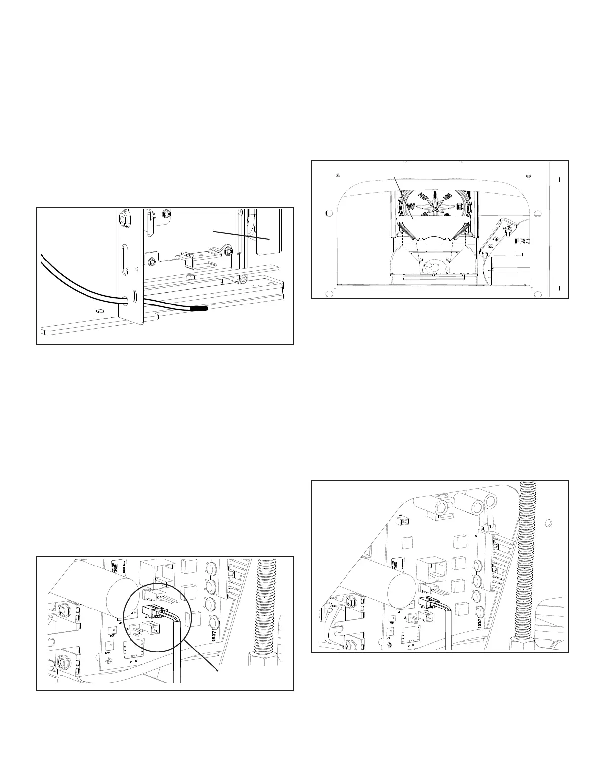
Oncethelocationhasbeendecided,runthewiringtothe
controlpanel.You’llneedtoremovethetwoterminalsfrom
the end of the sensor cable and replace them with the two
smaller terminals from the hardware bag. Plug the terminals
into the control board, Figure 5.15. These connections are
notpolarityspecic.
Note:Iftheroomsensorislocatedtooclosetotheappliance,
orinadirectpathofthedistributionair,Youmayneedto
elevate the temperature setting to maintain a comfortable
temperature level throughout the heated space.
If service is performed, the room sensor may need to be
disconnected to gain enough room to allow access to
the rear of the unit.
C. Electrical Connection Installation
Note:Iftheroomsensorisconnectedasareturnairsensor,
the wire should be connected long enough to allow this, but
not too long that it would get tangled or pinched anywhere.
Connecting the room sensor as a return air sensor
Insertthesensorendofthewirefromtherearofthemounting
frame through the hole as shown in Figure 5.14.
Note: For optimal temperature accuracy and performance,
use of the optional Wireless Remote Sensor is highly
recommended.
Place the sensor end so that the sensing tip is laying near
the ash lip rail. Figure 5.14.
Figure 5.14
Front Door
RoomSensor
E. Reminders
Always disconnect the power cord before the unit is
pulled from the mounting frame.
As you can see, the control board is easily accessible from
the rear with the body pulled out of the frame, even if it is
only pulled out several inches. Figure 17.
Always inspect the wiring harness and the 11 pin socket
(largewhiteatplugwhereallofthepowerwiresterminate.)
Always inspect the wiring harness where the wires transfer
from the control to the rear inside of the body.
Makesuretherearenowornorfrayedareas.
Figure 5.17
Figure 5.15
J7 Terminal
Slidetheunitintothemountingframemakingsurewiresare
clearoftheframeandstovebody.Snaptheleftandright
spring latches to secure the stove and remove the service
railkit.Re-installthemedallion.
D. Flame Guide
Installthecastironameguideontopoftheburnpot.Make
surethattheameguideisfullyseatedontheverticalsides
of the burn pot and that the back of the guide rests against
the body of the stove. Figure 5.16.
Flame guide
Figure 5.16
 Loading...