9
Verify that the available electrical power supply and the network
frequency correspond to the required operating current taking into
account the appliance's specific location, and the current required to
supply any other appliance connected to the same circuit.
ENPI4M 230V +/- 10 % 50 Hz 1 Phase
ENPI6M 230V +/- 10 % 50 Hz 1 Phase
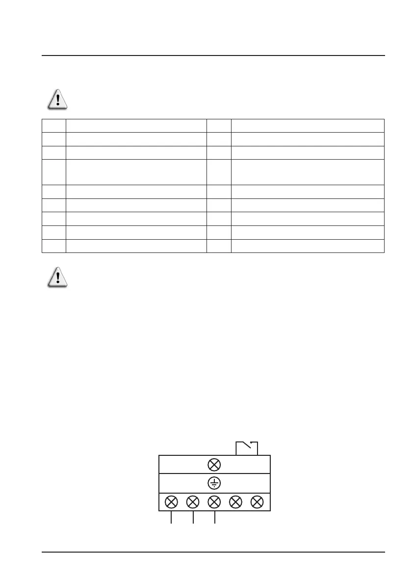
See the corresponding wiring diagram in the appendix.
The connection box is located on the right side of the unit. Three
connections are designed for the power supply and two are for
controlling the filter pump (Enslavement).
3. INSTALLATION AND CONNECTION (continued)
3.4 Electrical connection
F NF C15-100 GB BS7671:1992
D DIN VDE 0100-702 EW EVHS-HD 384-7-702
A ÖVE 8001-4-702 H MSZ 2364-702/1994/MSZ 10-553 1/1990
E UNE 20460-7-702 1993,
RECBT ITC-BT-31 2002
M MSA HD 384-7-702.S2
IRL Wiring Rules + IS HD 384-7-702 PL PN-IEC 60364-7-702:1999
I CEI 64-8/7 CZ CSN 33 2000 7-702
LUX 384-7.702 S2 SK STN 33 2000-7-702
NL NEN 1010-7-702 SLO SIST HD 384-7-702.S2
P RSIUEE TR TS IEC 60364-7-702
Electrical installation and wiring for this equipment must be in
conformity with local installation standards.
Dry contact 16 A max
potential free.
Priority heating function
L N 1 2
= = = =
Power supply
230V / 50Hz
K2
 Loading...